3D Cutting
The CNC machine has some good options for cutting simple but large 3D parts. Careful use of the settings is important here to get good results. Use these guides for 3D file setup:
The CNC machine has some good options for cutting simple but large 3D parts. Careful use of the settings is important here to get good results. Use these guides for 3D file setup:
To begin to create a 3D part, meaning any shape that is not a flat design or simple prism, you will want to create the file outside of Aspire first. There is some modeling functionality in Aspire but it will be much easier to create the part with a different software.Once you have your 3d part created, export it as an .obj or .stl file.
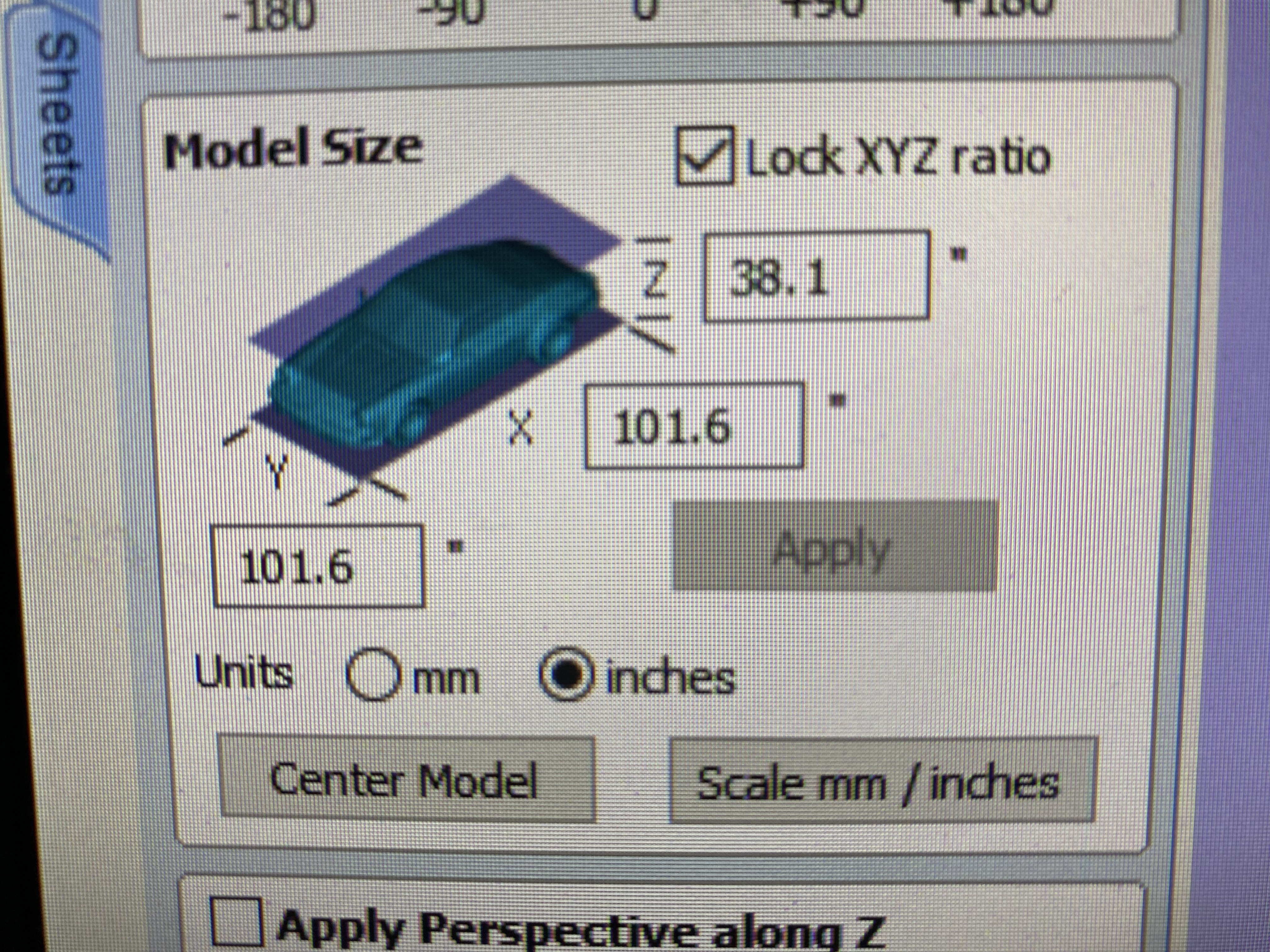
Once you have your file, open it with Aspire, edit the job settings as you would with a 2d part, and you will have your file, likely much larger than you intended.
To fix this you should change the dimensions in the options box that appears on the side of the screen.
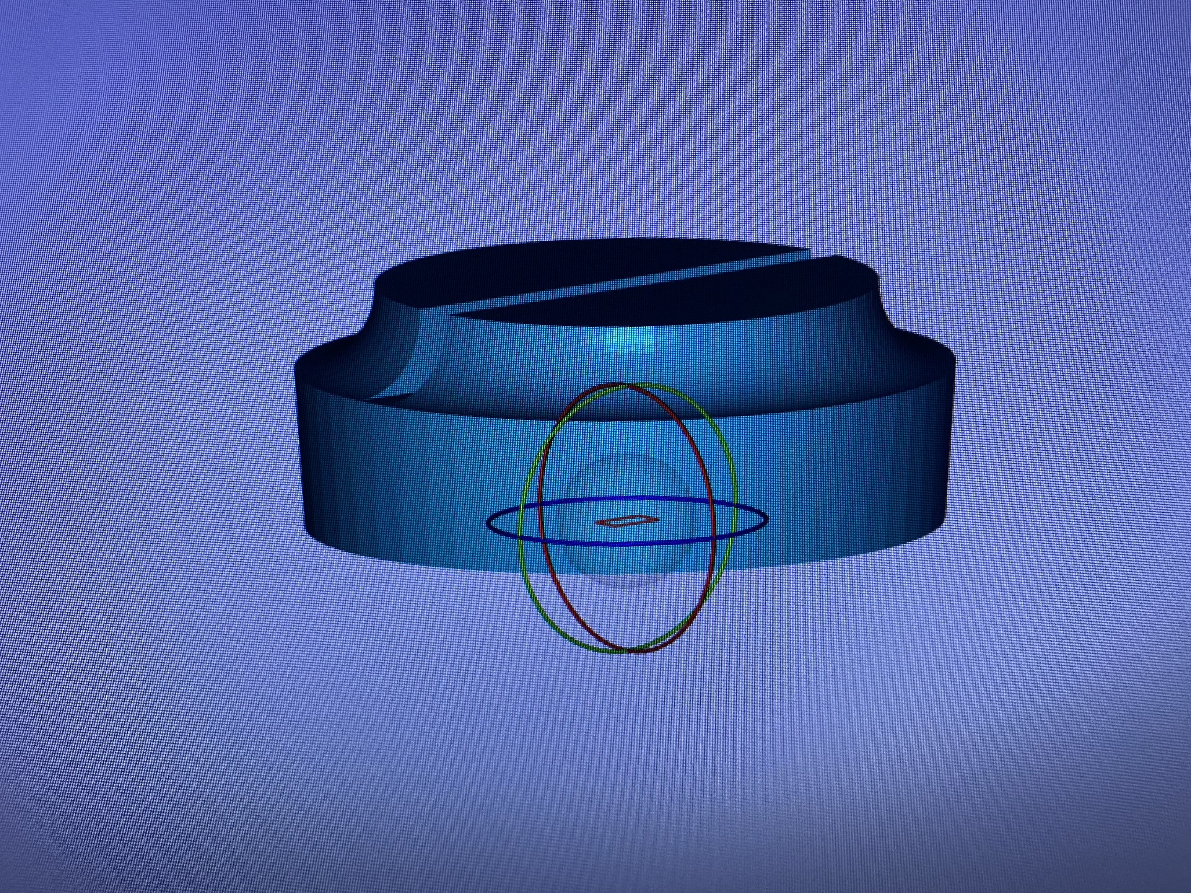
Within this box you can also rotate it with the profile buttons and the boxes for rotation. Keep in mind that the Shopbot can only cut downwards and not to the side, so keep in mind how your model is oriented and you will have all of the holes you intended.
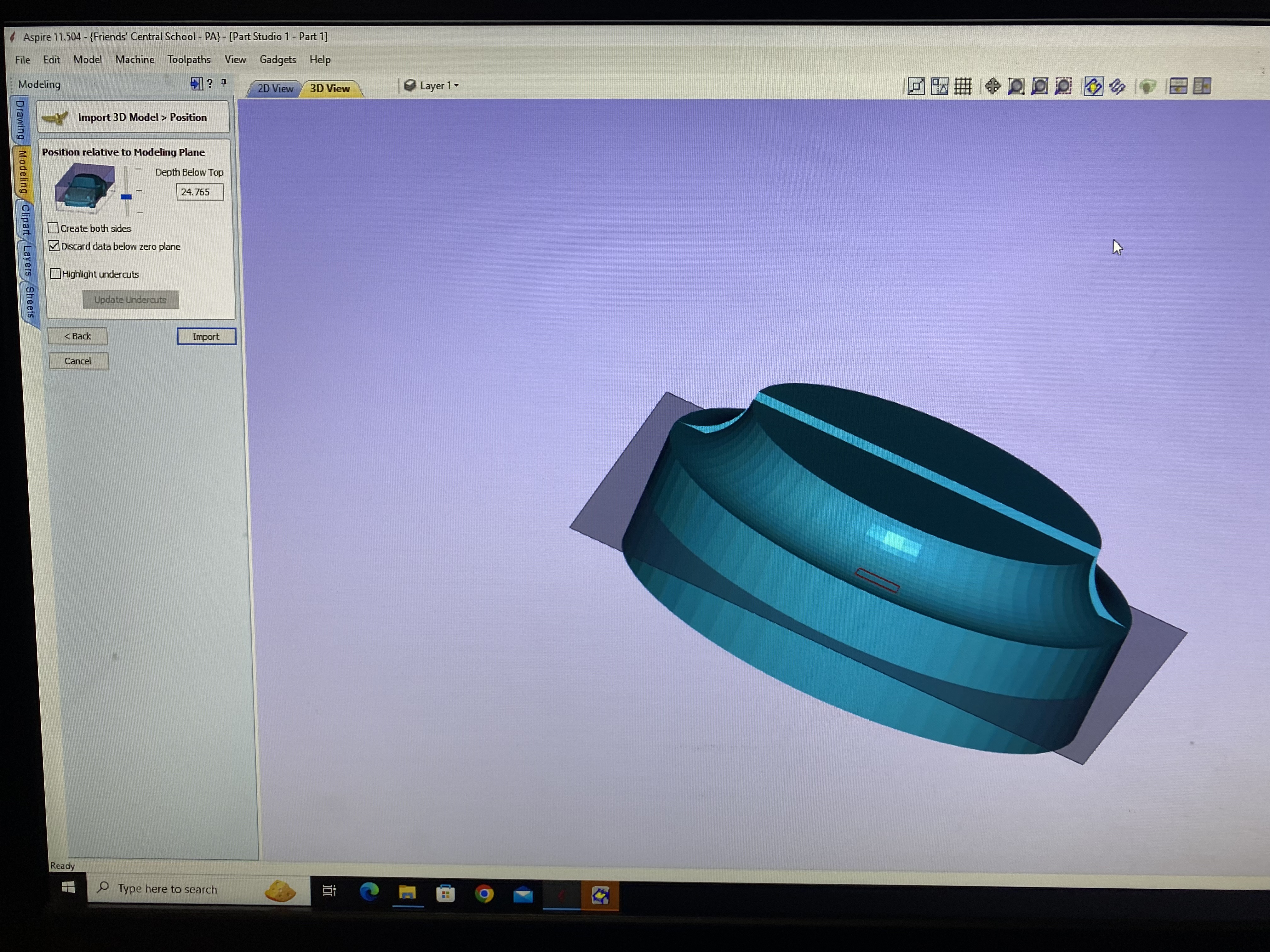
When you are satisfied hit the Position And Import button.
Since the Shopbot cannot cut both the top and bottom of a piece at the same time, it will cut the top and bottom halves separately. You can adjust this by changing the number in the second option box.
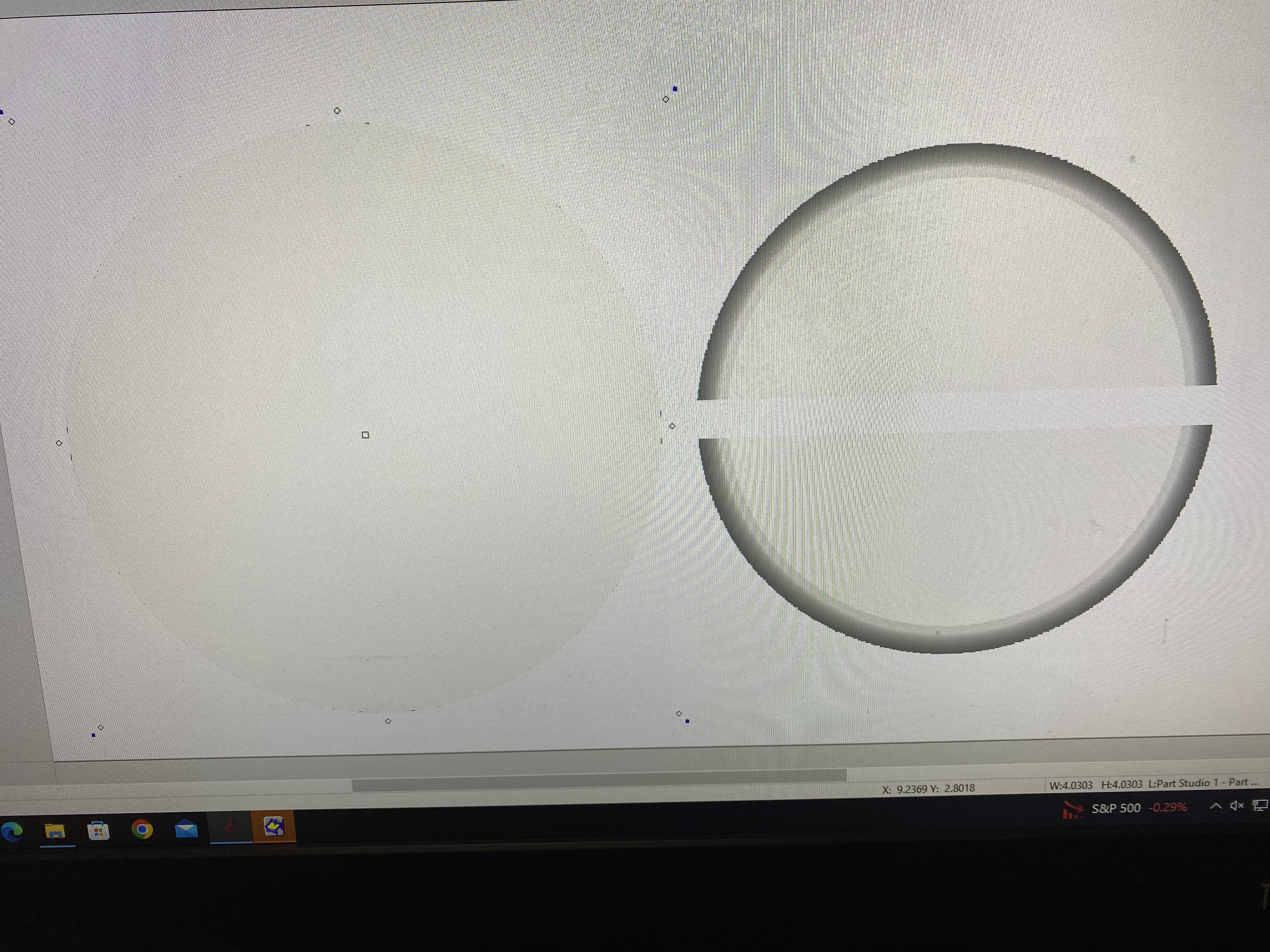
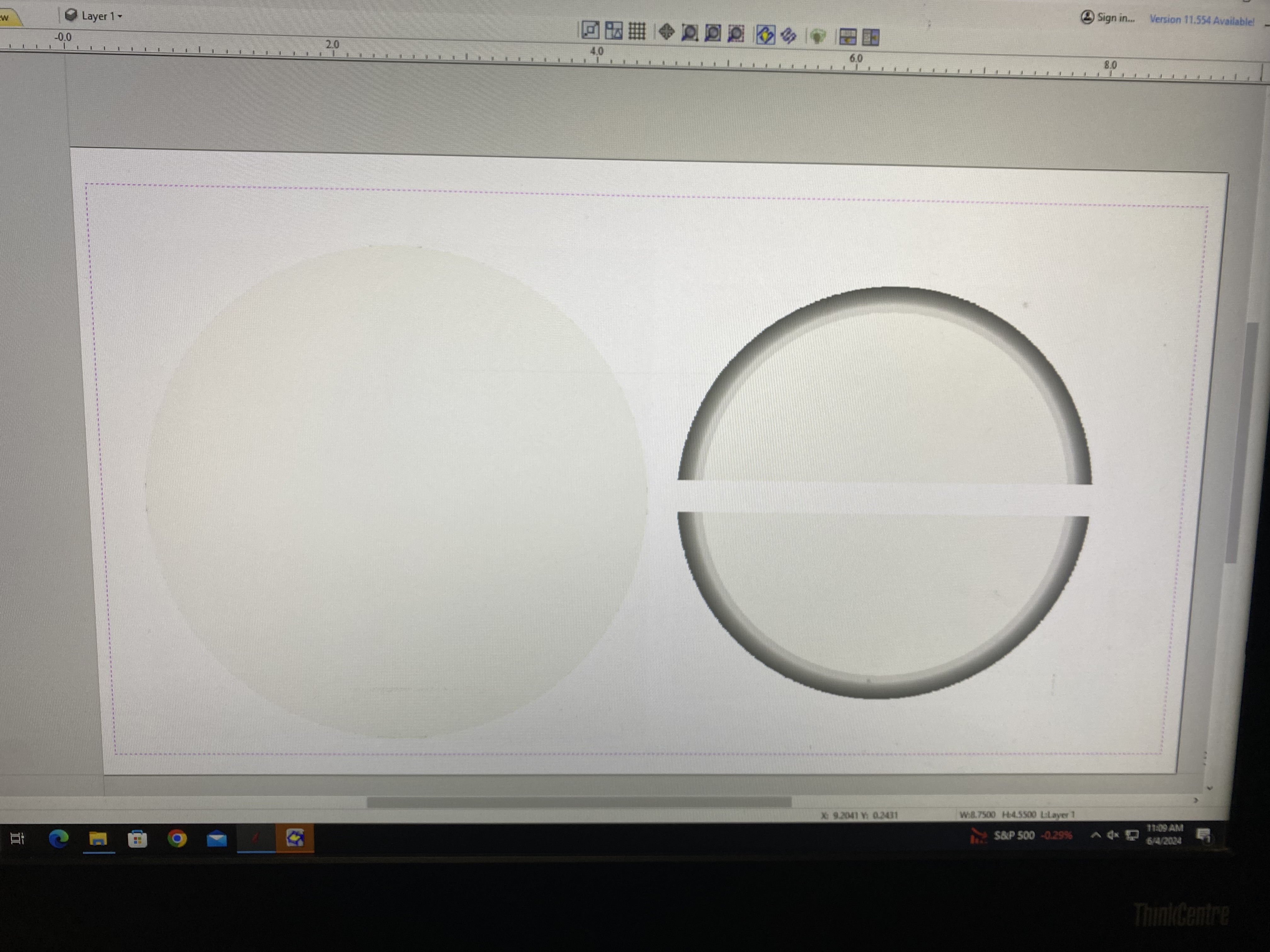
When you do that, the models will appear on top of each other in the 2d view, choose the move tool (cursor with a cross) and move one of the 2 objects away so they do not overlap.
Next go to the drawing tools and get the rectangle tool. Create a rectangle around both of your parts.
Then move to the Smooth and Rough Carving section.
Once you have your file set up correctly, select both of your pieces and the rectangle around them and select the rough machining toolpath.
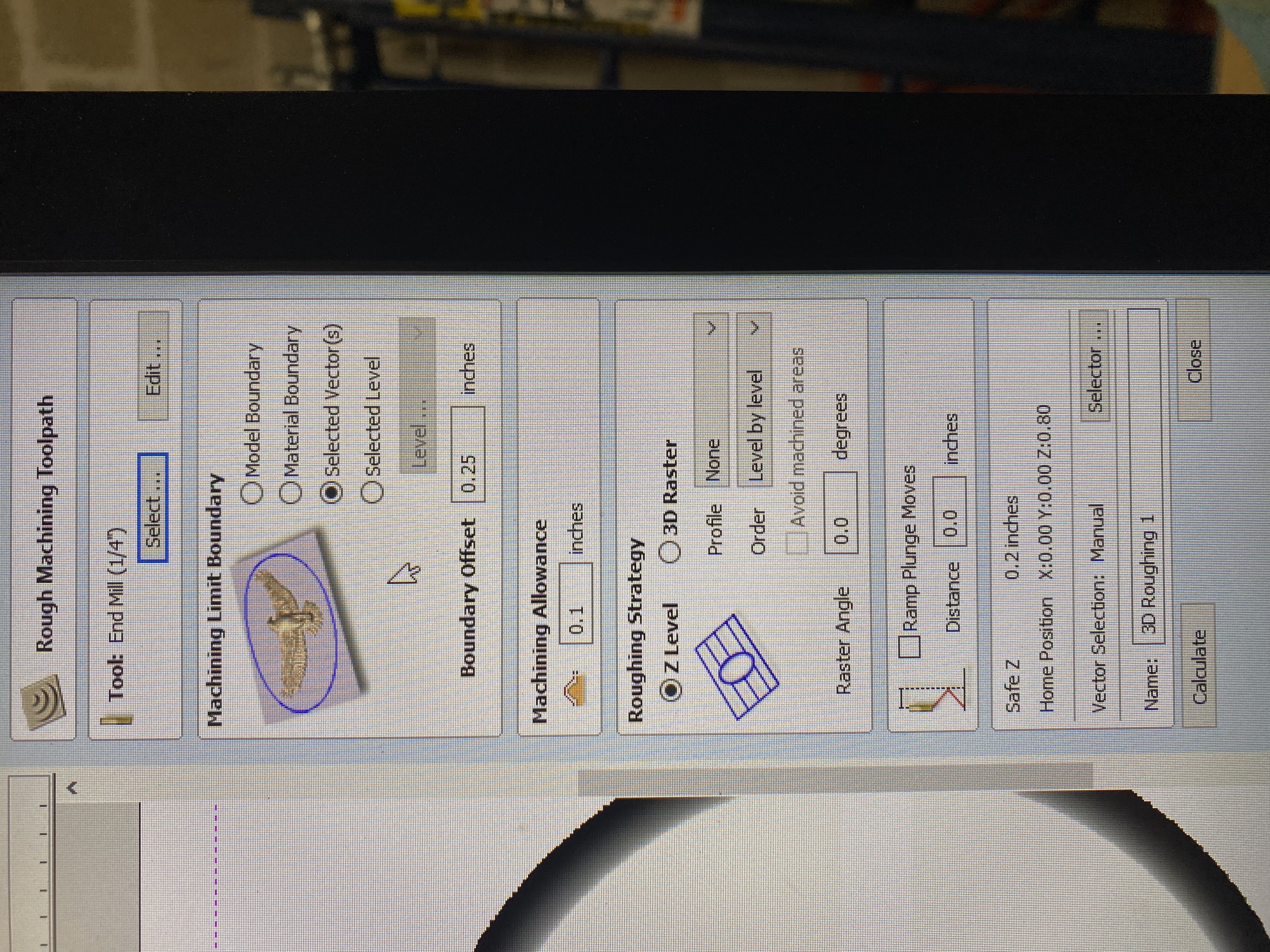
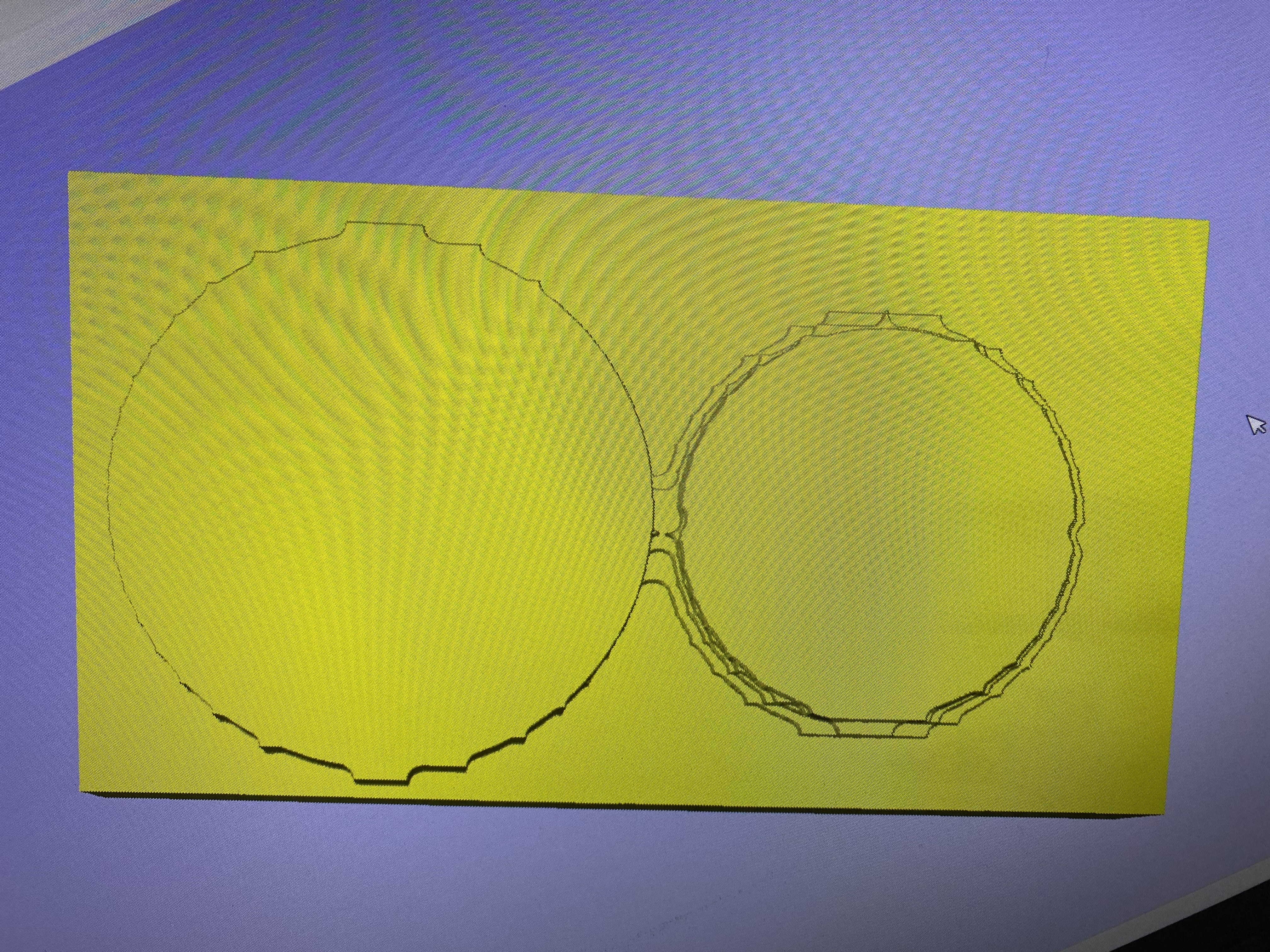
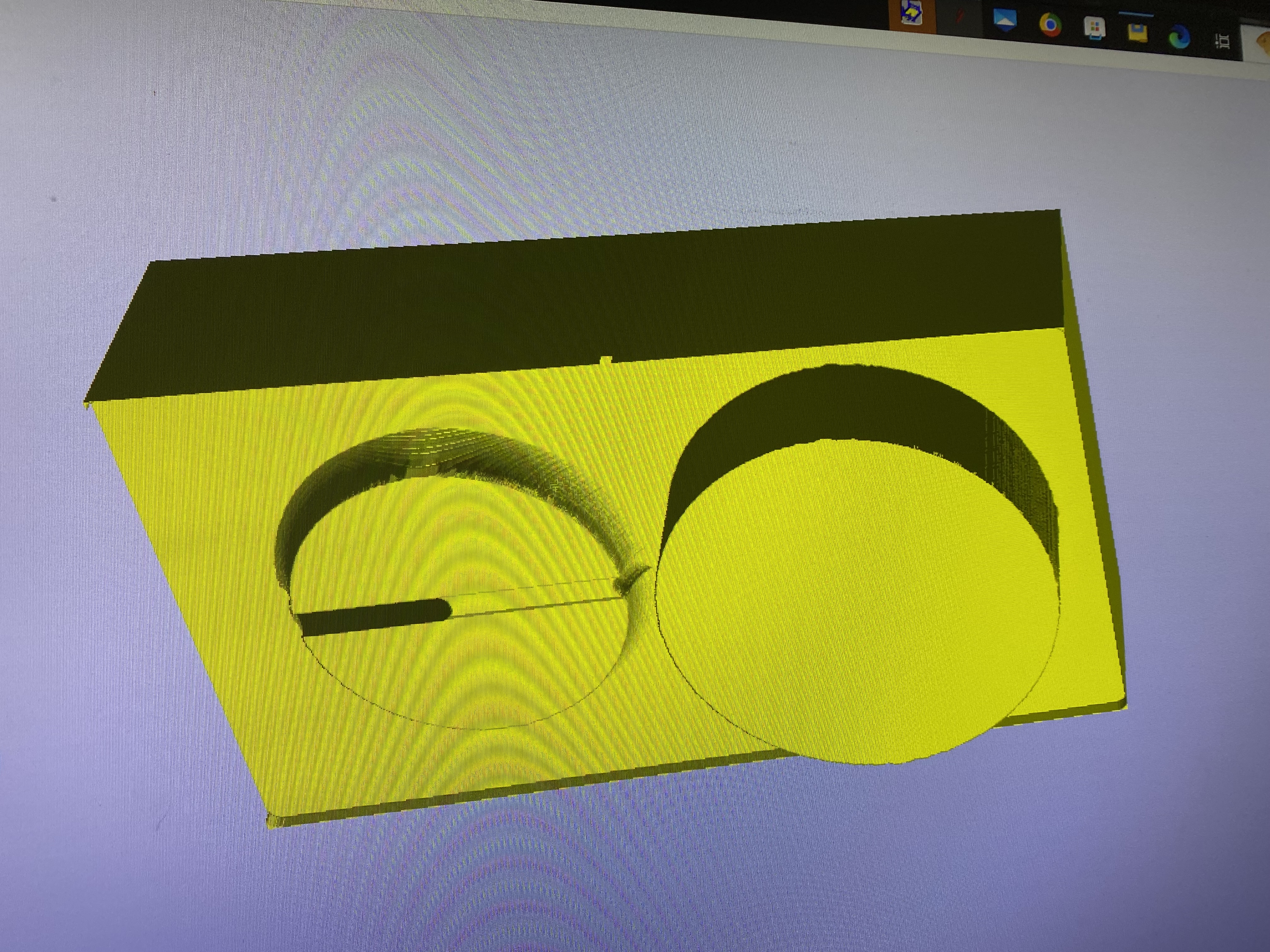
Select your bit and make sure that `Machining Limit Boundary is set to “Selected Vectors.” Then Hit calculate. Your toolpath should look like a rough outline of your shape
Now go back, select both pieces and the rectangle, and select Finish Machining Toolpath.
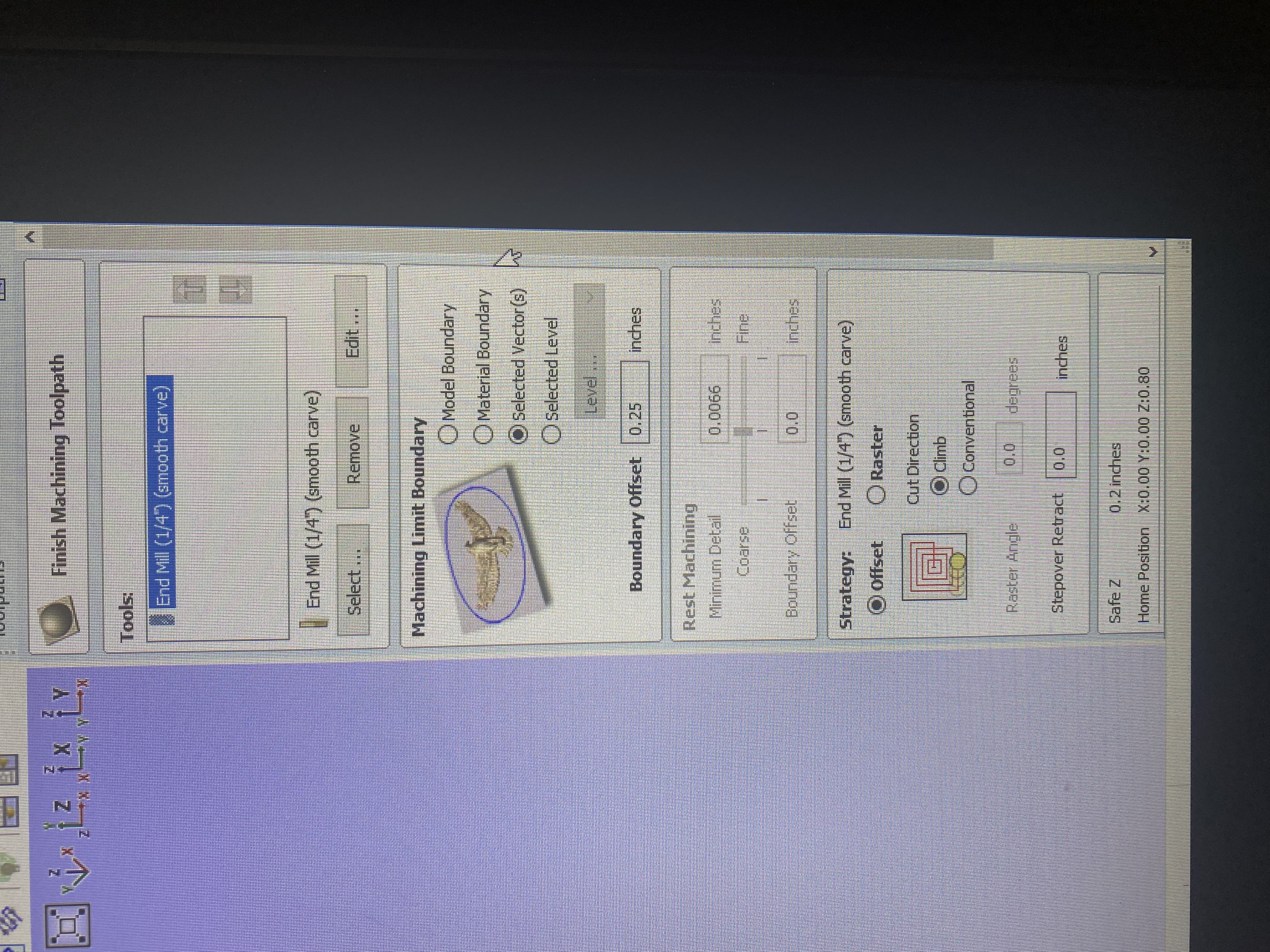
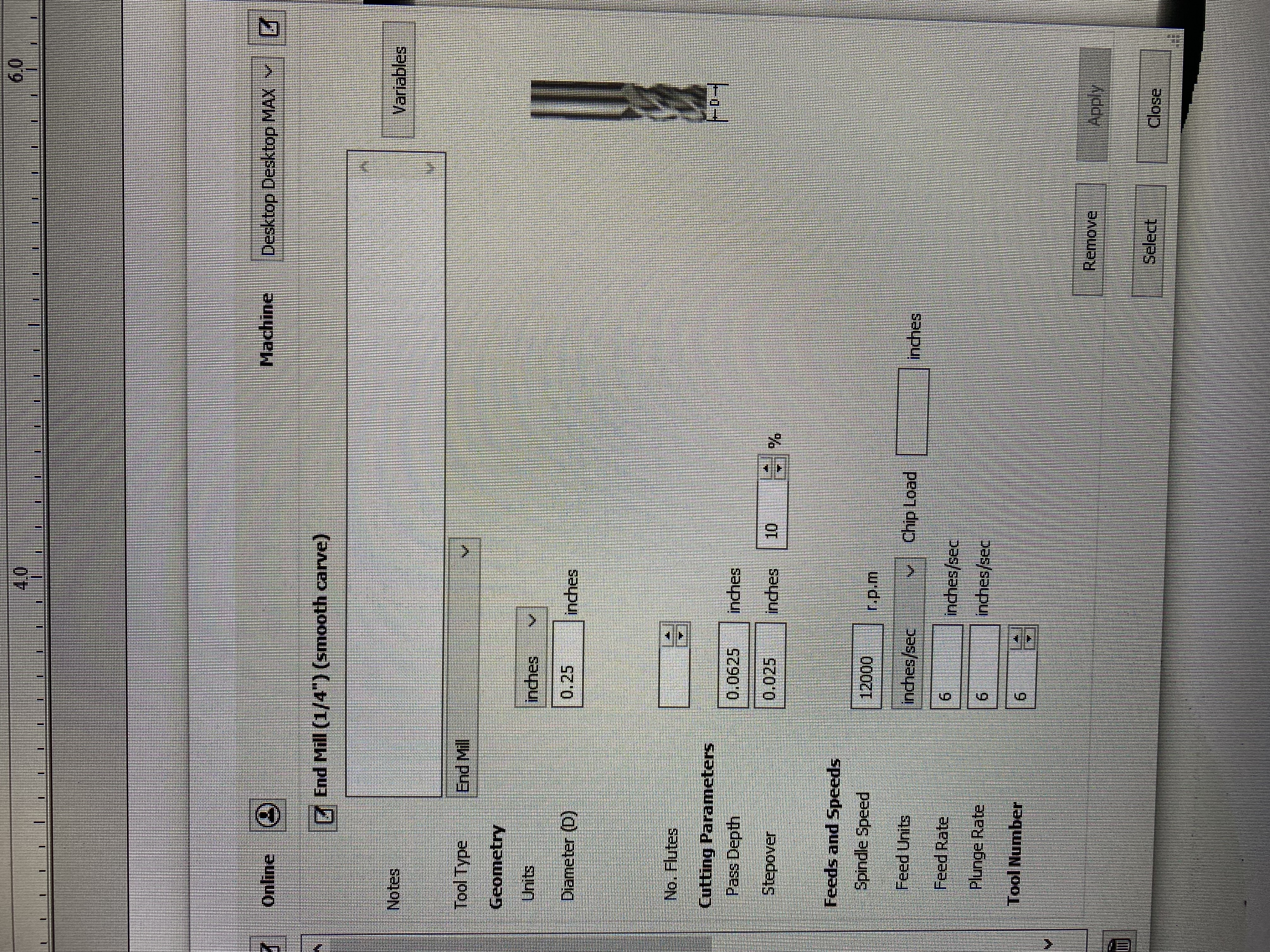
Now for the bit selection, hit Select and then look for a bit that is the same size as the one you used for the first path, but says (Smooth Carve) on the end. If this bit exists, simply select it and use it. If not, create a new bit with the same settings as your original bit, but with a Stepover of 10% or less, a spindle speed of 12000 RPM, and a feed rate and plunge rate of 6. Rename it the name of your bit followed by “(Smooth Carve)”. Then select that bit you just made.
Make sure that `Machining Limit Boundary is set to “Selected Vectors” and calculate your path.
You now have your cut file, and you are free to cut like any other piece. Go to the Securing Material section.