Uploading Files
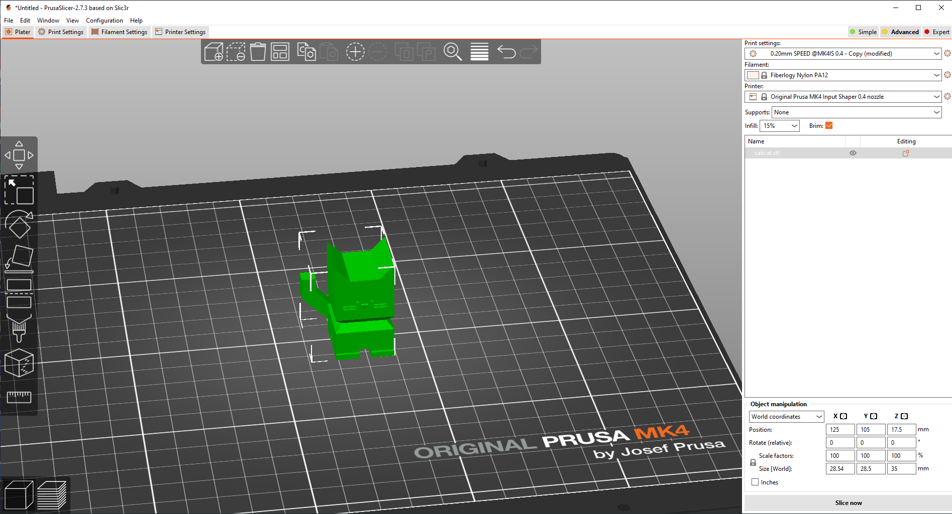
To upload files to the Prusa Printers first get the stl, obj, or other 3D file type and open it with PrusaSlicer either through opening through File Explorer or dragging the file into the PrusaSlicer application, or clicking the (

Once the file loads in, you can move it around the buildplate and change it to your likings, or upload more files by dragging them into the application window.
Tools
In the top menu you will see a list of options.
(

(

(

(

(

(

(

(

(

(

(

(

variable layer height menu which is beyond the scope of this guide and should not be used without a more comprehensive understanding of the printers.
Moving
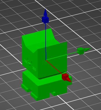
To move the print around the print bed, first click the item you wish to move, then either drag your shape to its intended position, or click the (

Once that happens you can either move it on the main axis by dragging those arrows, or just grab and drag the object to wherever you want it.
You can also set its exact position with the menu on the bottom right of the screen.
There you will also see a menu with two options World Coordinates and Object Coordinates.
World Coordinates lets you set position relative to the bed, with 0,0 being at the bottom left corner.
Object Coordinates lets you shift the object from its current position and will move it as far as you put in. You can also switch to measuring in inches by checking the inches box.
Scaling
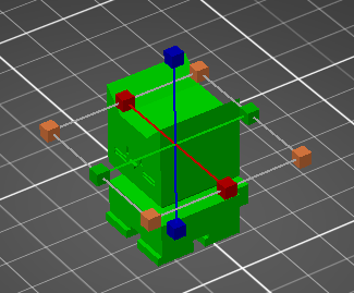
To scale your object, select the object, then select the (

You can grab any of the three to stretch the object in the direction of that line, or instead grab one of the orange boxes to stretch in all directions equally.
You can also set its exact scale with the menu on the bottom right of the screen.
Scale Factors allows you to set the scale relative to the original object.
Size \[World\] allows you to set the numeric size along all three axis. You can also switch to measuring in inches by checking the inches box.
If the lock icon is closed, the object will retain it’s original proportions and scale axis equally. If it is open you can manipulate the three separately.
The rewind icon will set the object to it’s original dimensions.
Rotation
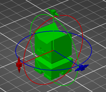
To rotate your object, select the object, then select the (

You can grab these rings and rotate them to rotate the object how you would like it to print. Keep in mind where the front of the bed is, signified by where it is written Prusa MK4.
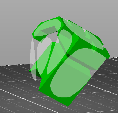
It is recommended to rotate the object so that the least amount of overhang is achieved:
And the maximum amount of the print is touching the build plate:
You can also set its exact rotation with the menu on the bottom right of the screen.
Putting numbers in the text boxes will rotate the object in the direction of the arrows that appear as many degrees as you insert in the box.
You can also click the (

Cutting
To cut your object in 2 pieces, hit the (

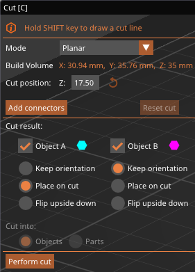
In the menu you will see a selection box labeled Mode. Inside there are two options, Planar and Dovetail.
Planar
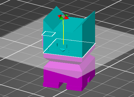
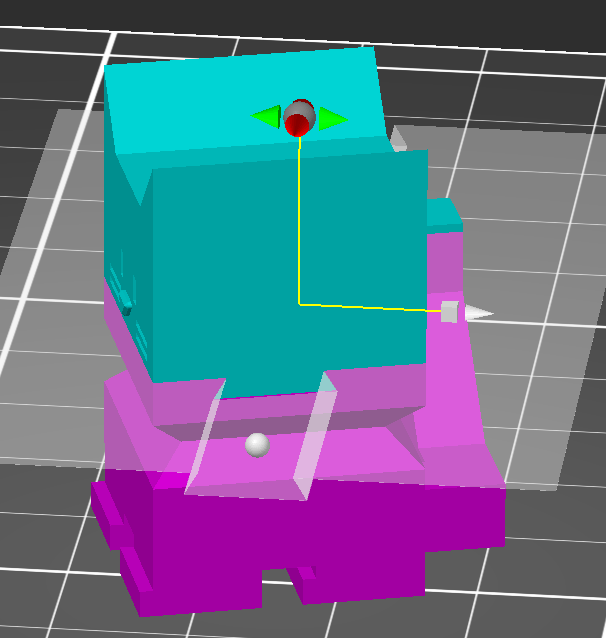
When you select planar, you should first select where you would like to cut the file. The plane will automatically appear and shade the two halves of the object different colors. To adjust this cut, you can either drag the red and green arrows to tilt the plane, or grab and drag the grey ball to move the plane.
You can also set the height of the cut off of the buildplate automatically in the menu.
This will create a smooth cut into two pieces.
If you want to instead have a more secure way of joining these pieces after you cut, press the Add Connectors button.
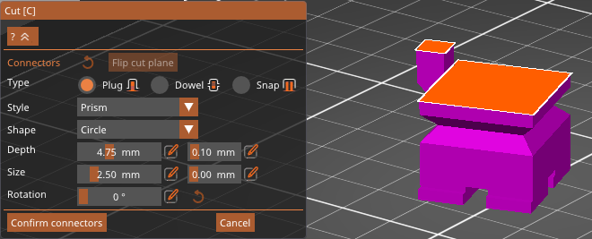
From there it will hide one of the two halves, and allow you to place connectors. You will see 3 options for the type of connector, Plug, Dowel, and Snap.
Plug creates a small protrusion from one side, and a matching hole in the other. You can select whether you would like a prism or frustum shape:
As well as what shape you would like it to be, triangle, square, hexagon, or circle:
Dowel creates holes in both halves of the print as well as a small dowel to join the two.
Again you can choose the shape of the dowel, triangle, square, hexagon, or circle:
Snap creates a small mechanism which will snap into a hole in the other piece.
For all of these options, you can change the depth out of or into the piece, the horizontal size of the peg, and the rotation around its center.
For the snap you can alter the bulge of the top section and space between connectors. Hitting the rewind icon will pu tit back to default settings.
Once you are happy with the settings, you can click anywhere on the orange surface to place the connector where you click.
Hit confirm connectors once you are happy with the connector position and settings or cancel to return to the cut menu.
Dovetail
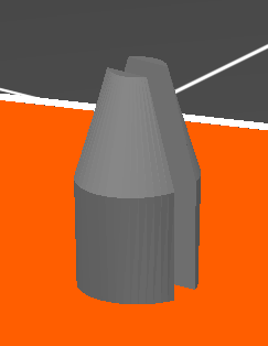
Dovetail will create a unique joint between the two pieces, where one will be able to slide into the other.
The plane will automatically appear and shade the two halves of the object different colors. To adjust this cut, you can either drag the red and green arrows to tilt the plane, grab and drag the white ball to rotate the groove, or grab and drag the grey ball or cube to move the plane.
You can also set the height of the cut off of the buildplate automatically in the menu.
From there you can adjust the settings of the dovetail joint, with the sliders provided. Hitting the rewind icon on any slider will set that slider back to it’s default position.
Cut Result
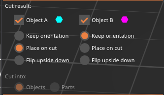
Below the other settings, you will see a section named Cut Result. There you will see a column for each half of the cut. If the check box is selected the cut will generate that pice and not discard it.
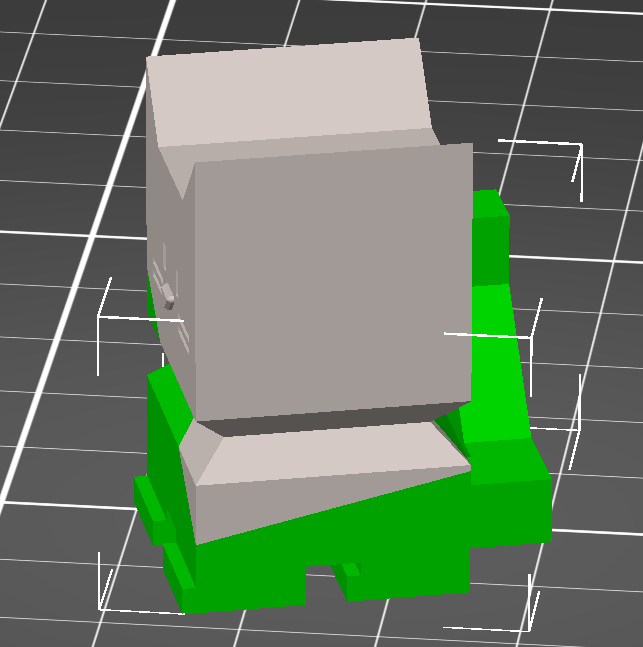
You can then select how to place the object once it cuts. Keep Orientation will keep the object as it is before that cut. Place On Cut will lay the object along the plane of the cut. Flip Upside Down will invert the object.
If you have selected planar and not added connectors, you can at the bottom select to cut into parts instead of objects, which will leave the two sides connected but allow them to have their settings edited separately with the left parts menu.
Support Painting
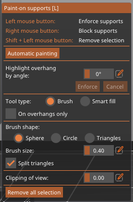
If you press the (

You can also automatically paint areas, edit where can be painted, and edit your “brush” shape in the menu below.
Seam Painting
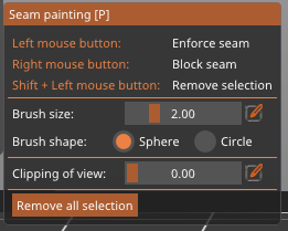
If you press the (

Clicking and dragging will force the printer to place a seam there, and right clicking and dragging will stop seams in that area.
You can also change the shape of your brush and view options in the menu that appears.
Measuring
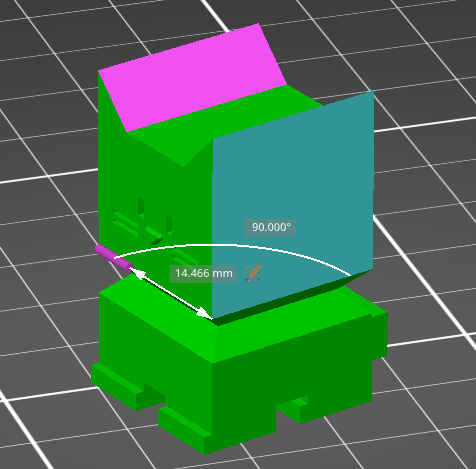
To measure your object, select the object, then select the (

When you measure a length, a (
 ) icon will appear, and allow you to change the length highlighted and scale the rest of the model to enforce that length.
In the menu you can either hit the Restart Selection button to clear your selection, or click the (
 ) icon next to the measures to copy the numbers there.
Done?
Once you are happy with the object’s placement, move to the Printer Settings section.
