Chapter 1
3D Printers
We haev a large collection of 3D printers here in the CID, where you can design and print anything you can imagine!
The pinters availible in the CID are:
We haev a large collection of 3D printers here in the CID, where you can design and print anything you can imagine!
The pinters availible in the CID are:
The FormLabs resin printer is the highest detail printer here in the CID and can create incredibly fine figures. Printing upside-down on the print bed, the FormLabs printer is one of the slower but more precise printers. To use it follow these guides:
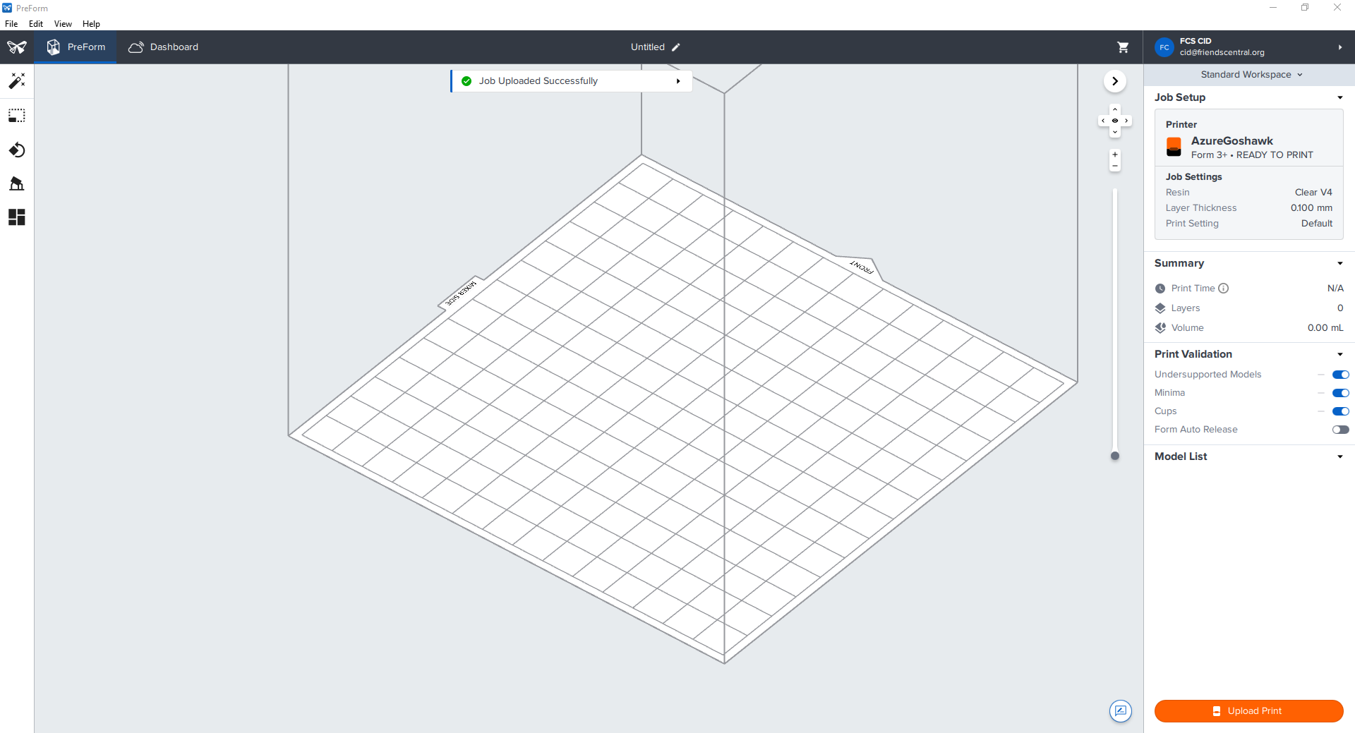
To upload files to the FormLabs printer first open the PreForm application.

Then drag and drop your intended file into the work area of the window
From here you have a few options about how to set up your print.
The simplest is to hit the ( ) icon and use
 One Click Print
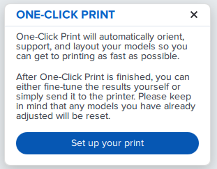
Hit the Set Up Your Print button and the app will automatically rotate your model and add supports for the best print generation.
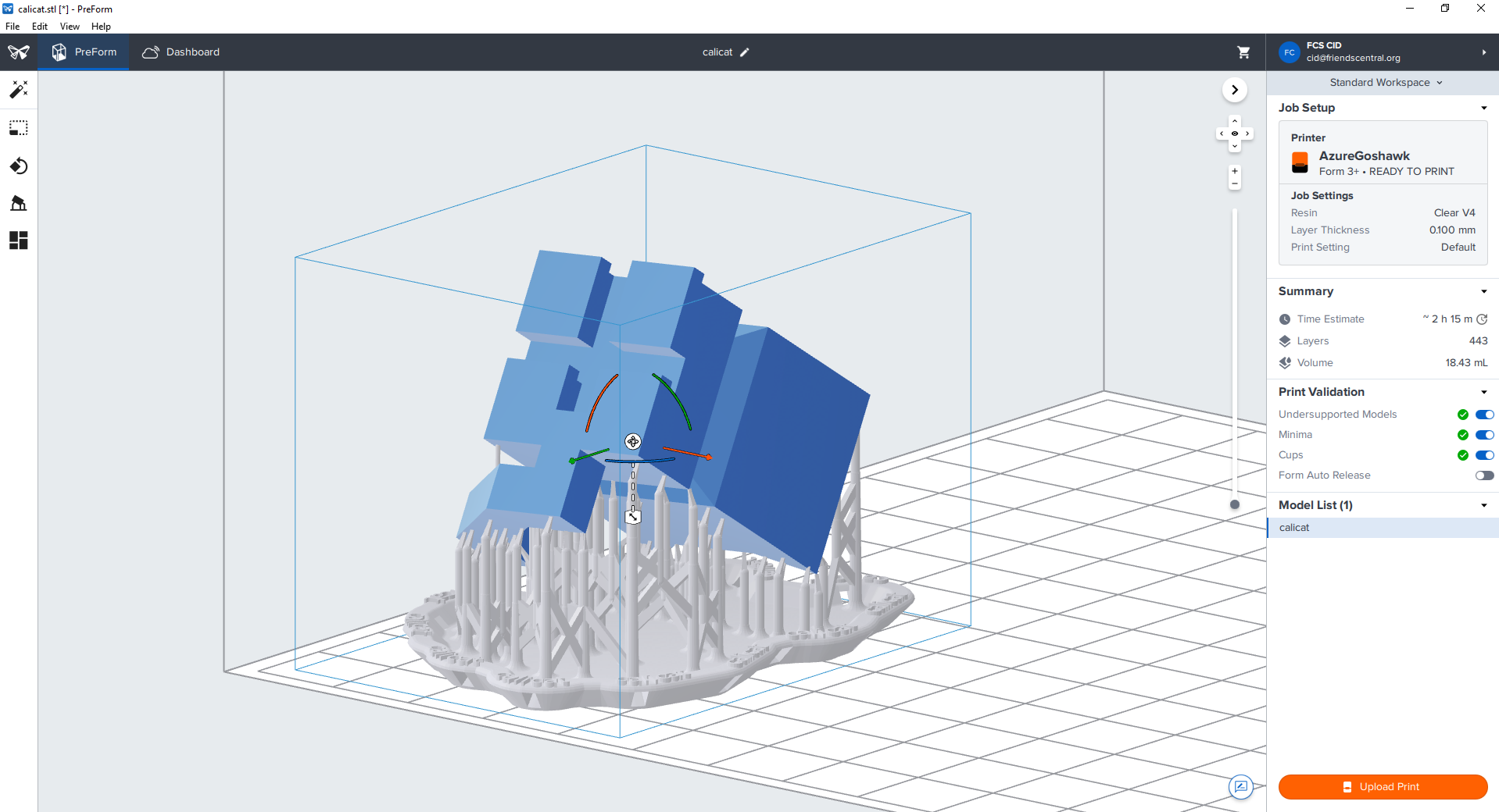
It will also pop up the printing menu, which we will discuss in the Printing section.
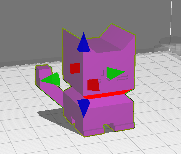
To move the print around the print bed, first click the item you wish to move, and you will see two arrows pop up around your shape, as well as 3 quarter rings.
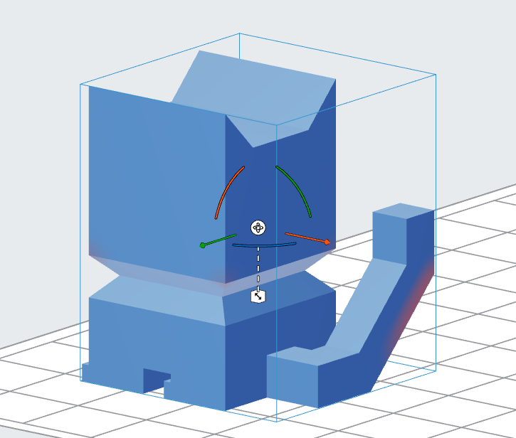
Once that happens you can either move it on the main axis by dragging those arrows, or just grab and drag the object to wherever you want it.
You can also rotate it by grabbing and dragging the quarter rings or the ( ) icon.
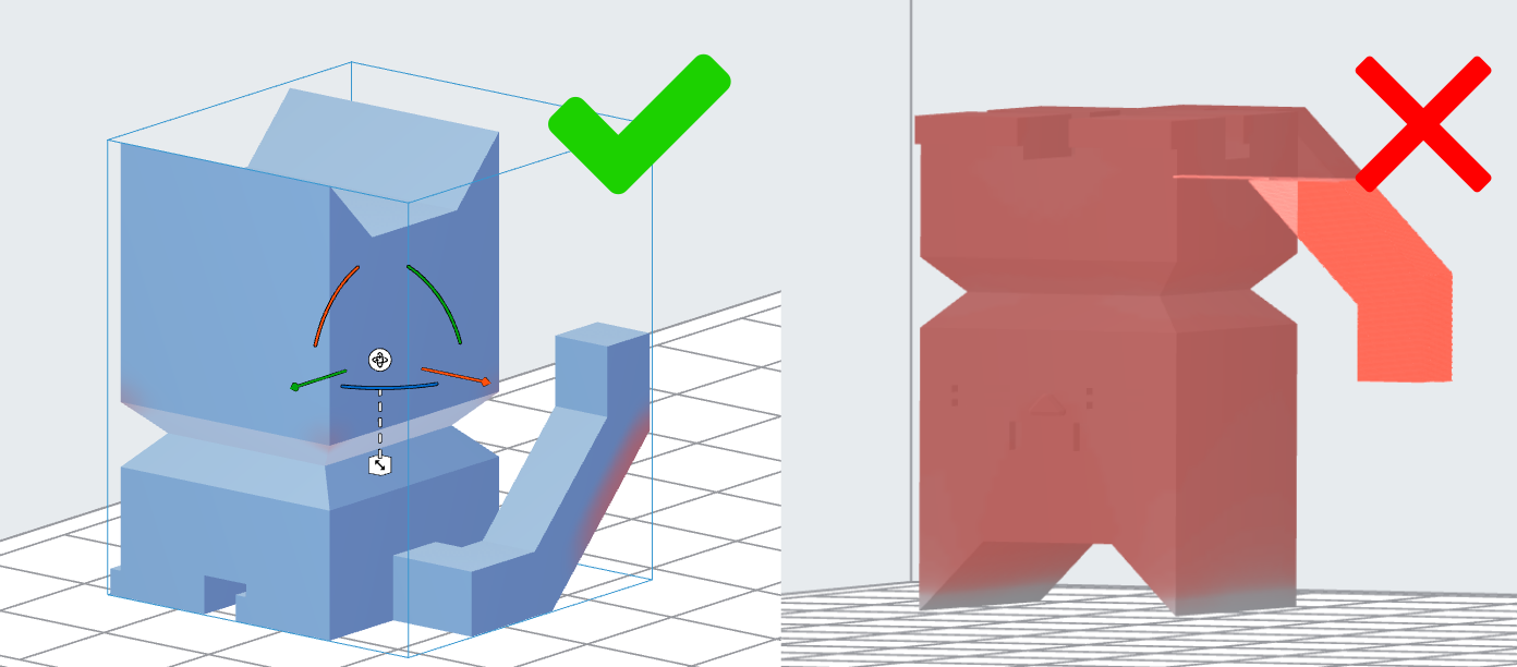
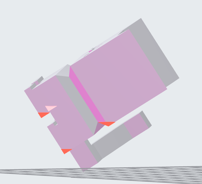
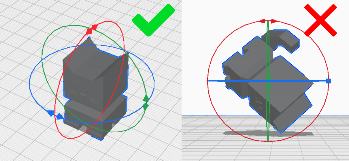
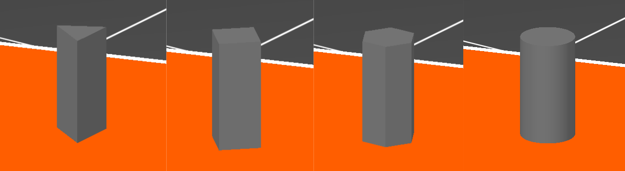
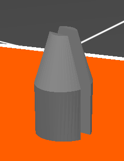
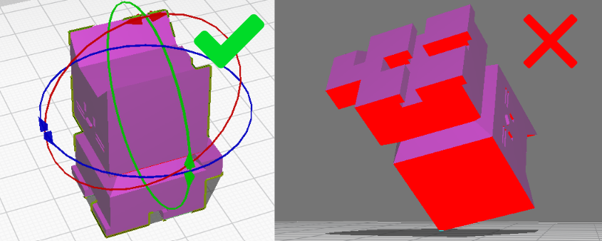
It is recommended to rotate the object so that the least amount of overhang is achieved:
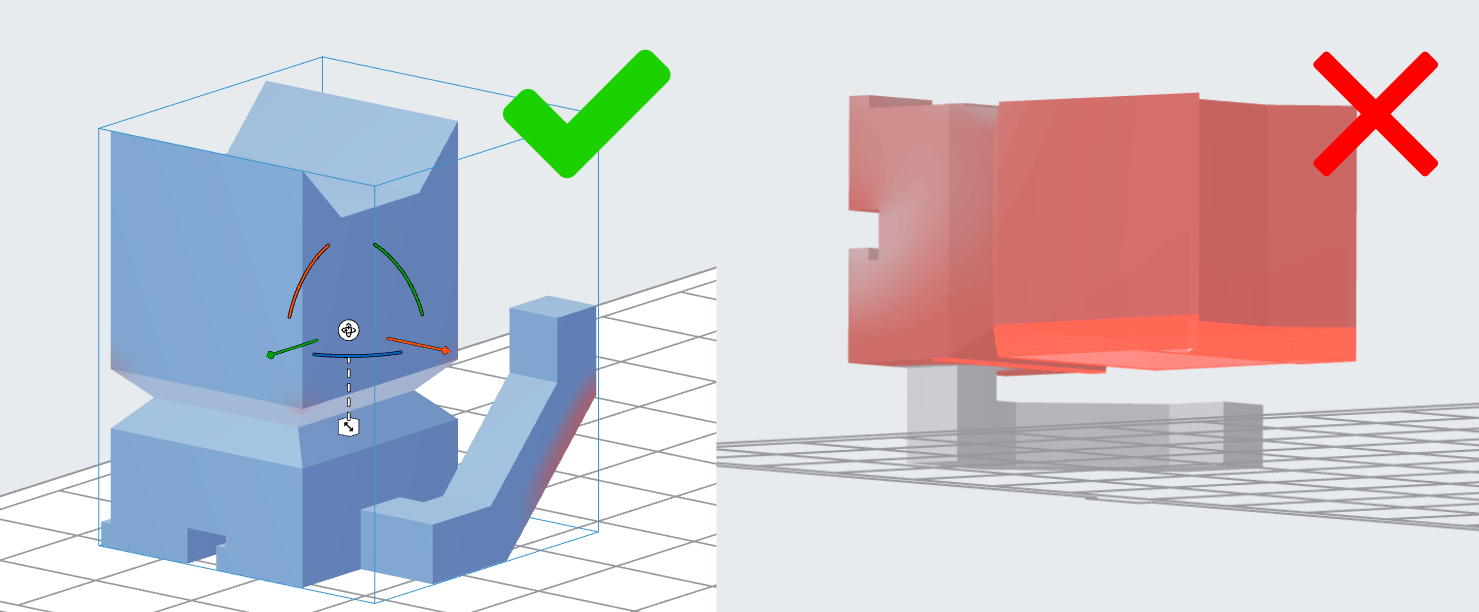
And there are no shapes that create cups:
Again a menu with certain options will also appear next to the ( ) icon.
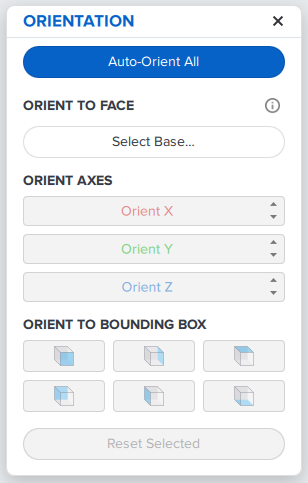
The Auto-Orient Selected will rotate the object to have the optimal setup.
The Orient To Face button will allow you to click on a face of the print and the program will lay it flat against the print bed such that the arrow that appears will point straight down into the bed.
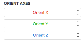
You can also edit its rotation more precisely by clicking the arrows next to Orient X, Orient Y, and Orient Z to rotate it around those axes.
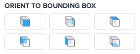
There also is a handful of options labeled Orient To Bounding Box. This will lay the face of the rectangular box around the object flat against the bed.
Finally the Reset Selected button will return the object to it’s original orientation.
To scale your object, select the object, then select the ( ) icon. A menu will appear next to the icon.
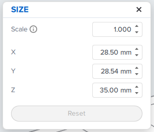
The text boxes allow you to set the scale of the object by a multiple of it’s current size and scale it evenly across all axis, or scale the axis separately to the size you specify.
The Reset button will set the object to its original dimensions.
Alternatively, when you select the object you can grab and drag the ( ) icon to scale it evenly.
To manage the layout of the bed, select your object and hit the ( ) icon. A menu will then appear.
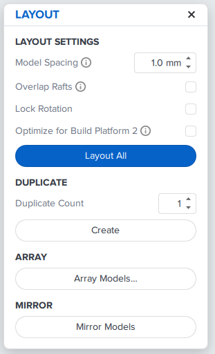
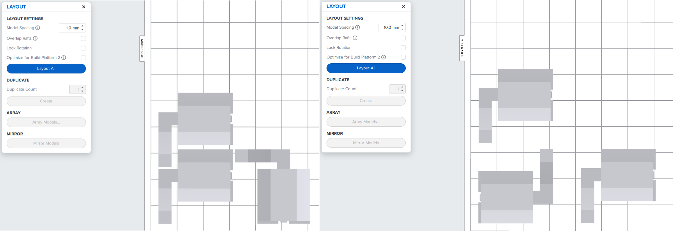
To automatically layout your objects, you can change the Model Spacing and choose whether to select Overlap Rafts and Lock Rotation. Then hit the Layout All button.
Model Spacing Will dictate how close the pieces end up after placement.
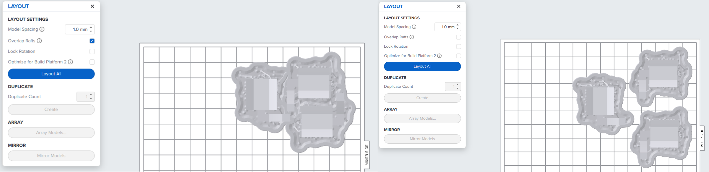
Overlap Rafts dictates if the support rafts can overlap.
Lock Rotation stops the program from rotating the models while arranging them.
To duplicate your model, first select how many copies you want, then hit the Create button.
Array will duplicate your models in a regular pattern, with a specified number of rows and columns and specified spacing.
Hit the Mirror Models button to mirror all selected models.
To generate supports for your model, hit the ( ) icon and a menu will appear. If you select an object or objects, you can generate supports only for the selected objects, or alternatively generate supports for all objects by not selecting any one particular object.
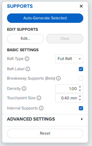
Firstly, you can automatically generate the supports by hitting the Auto-Generate All button.
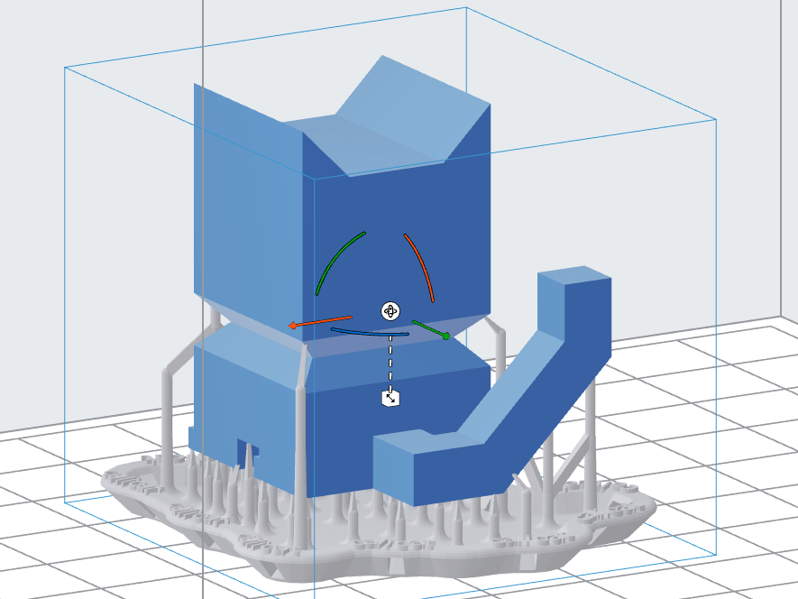
You can paint on supports by hitting the Edit button, but the details of that will not be covered here. It is recommended to use the Auto-Generate option instead.
You can edit the way supports generate in the Basic Settings section.
Raft Type will change how the support raft generates, either Full Rafts, Mini Rafts, or None.
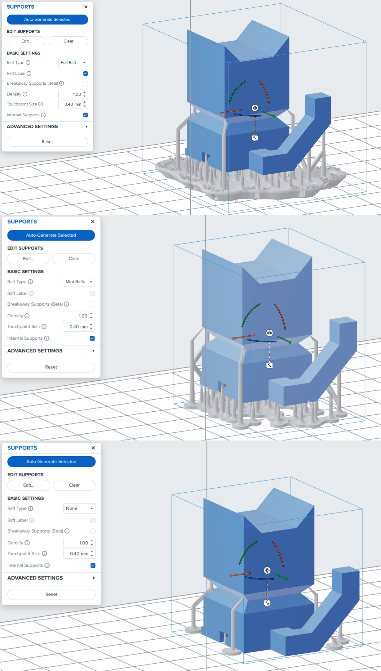
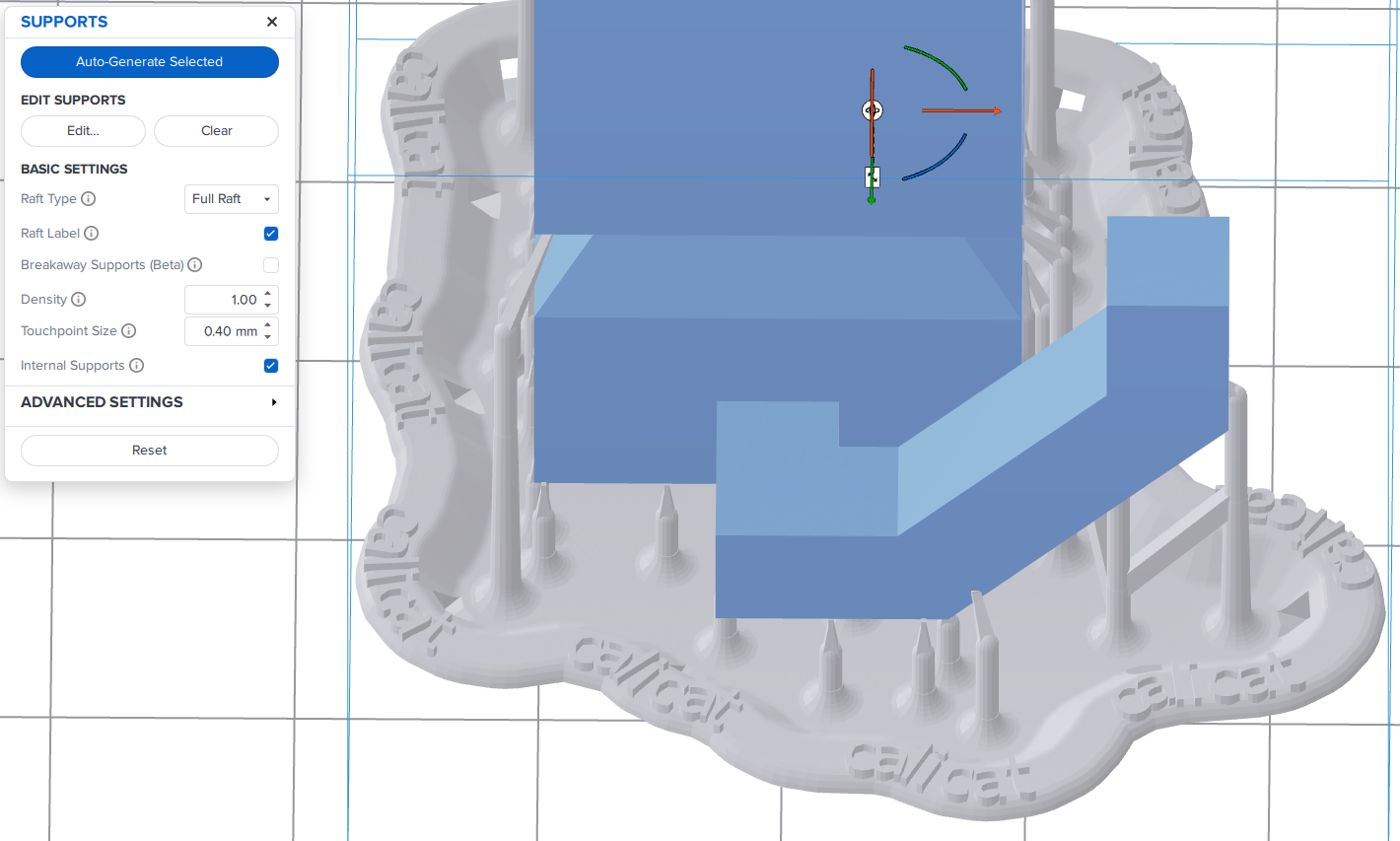
Raft Label will place the name of the object on the rim of the raft.
Density Changes how often the supports will be placed.
Touchpoint Size changes the area of the contact between the support and the object.
Internal Supports will generate supports between different layers of the object.
Advanced Settings has more particular details but will not be covered on this guide.
Hitting the Reset button will reset the objects completely.
Once you are happy with the object and support placement, move to the Printer Settings section.
Now that you have your print set up, click the Printer button in the top left.
Under the choose printer section, select the dropdown and select Form 3/3+.

Then underneath should appear a row named AzureGoshawk which you should select.

Select whatever material is currently loaded in the printer.
Layer thickness will change how fast the file prints as well as the resolution of the product. Use 0.1 mm for most prints, or smaller if you need super precise detail.
Don’t worry about the Other Settings as we do not have the hardware for those.
When you are happy with your settings, hit the Apply button in the bottom right and move to the Printing section.
Once you are ready to print, hit the Upload Print button and a menu will appear. This is the same menu that will appear when you use the One-Click Print feature.
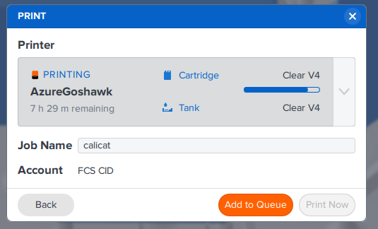
In this menu you can either press Add to Queue or Print Now.
Add to Queue adds it to the list of prints available on the printer.
Print Now starts the job immediately. Your object should print shortly.
Once the print has finished, go to the Removing From Bed section.
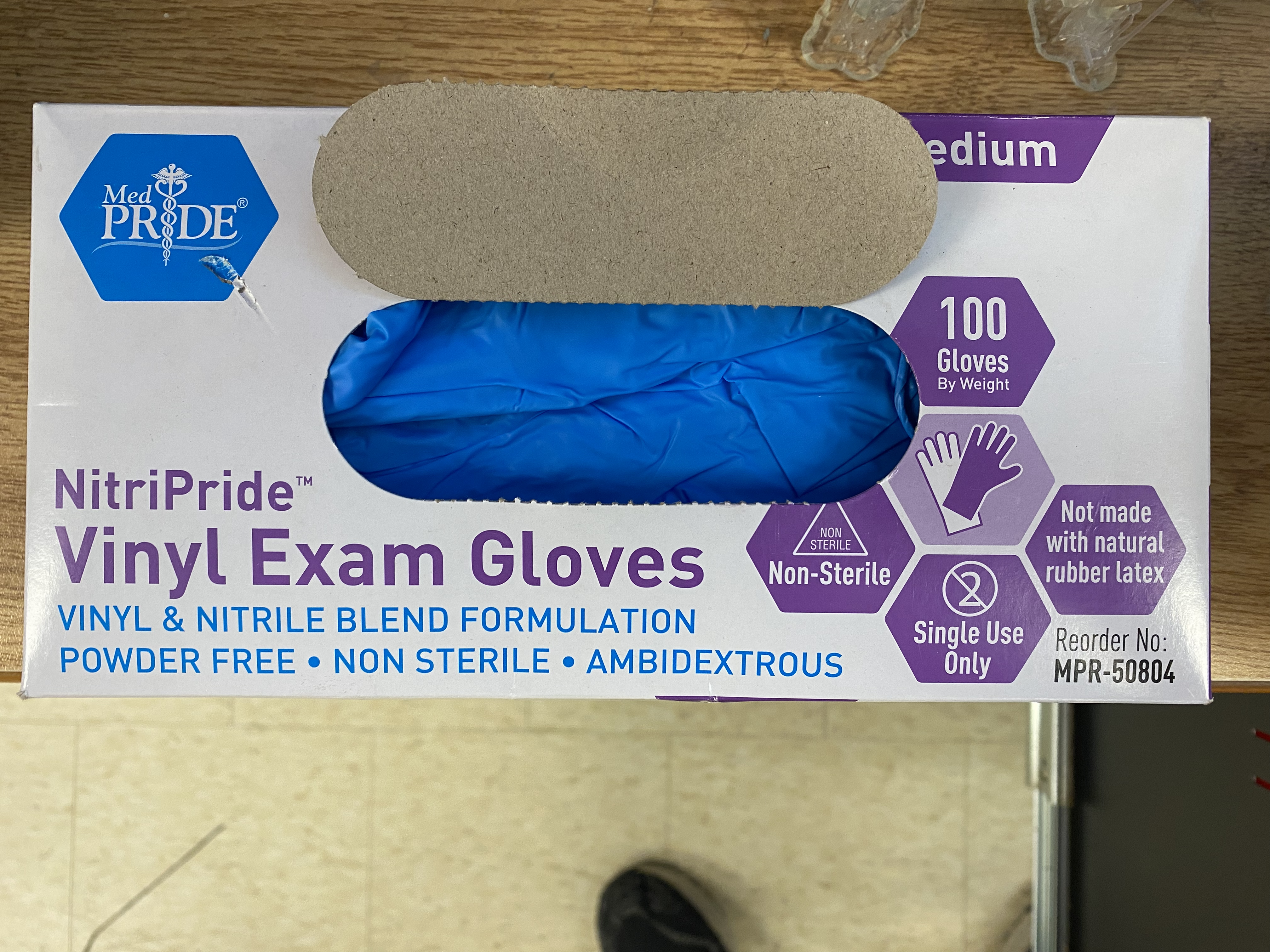
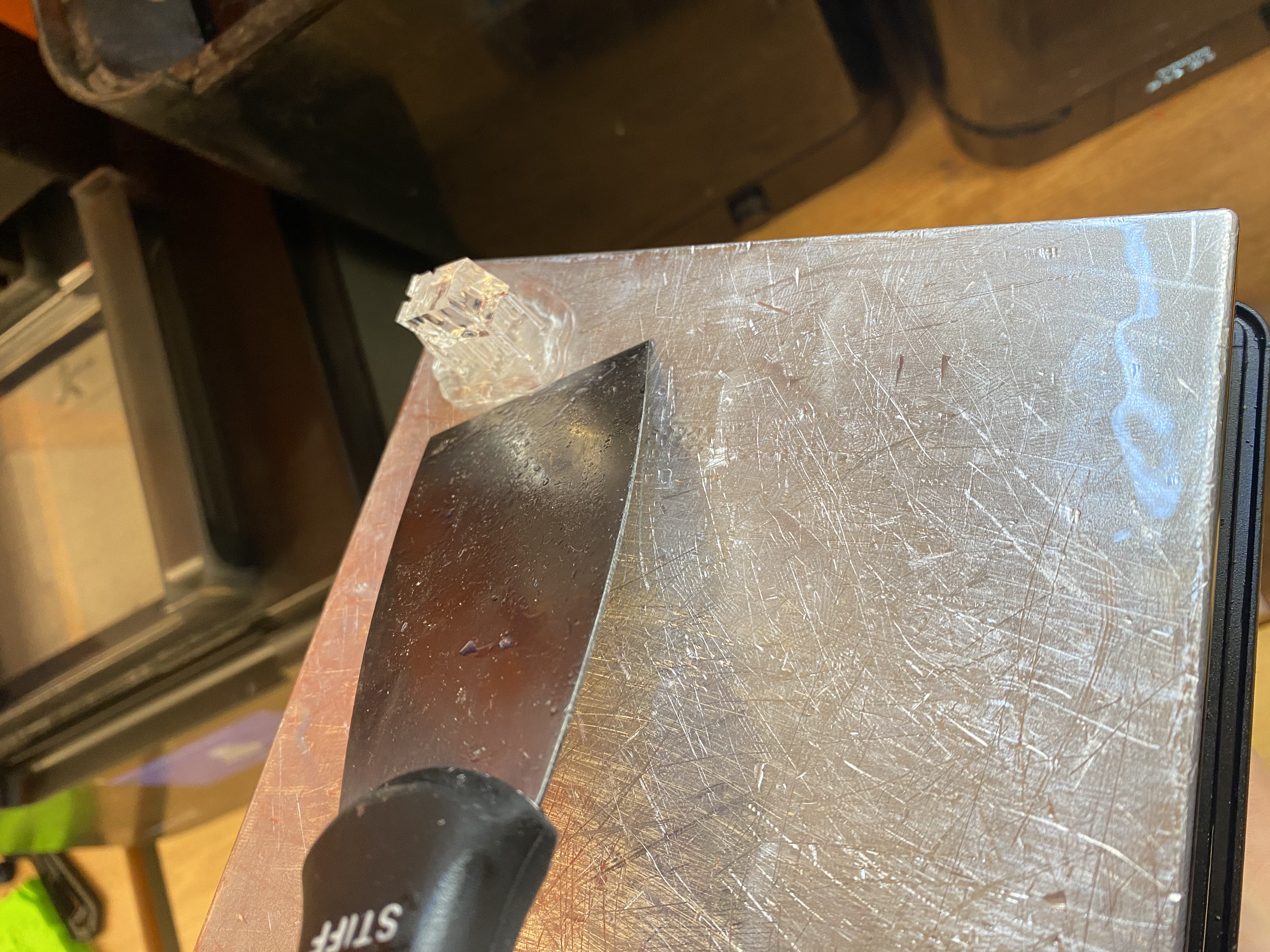
To remove the print from the bed, first put on latex gloves as resin can be harmful to your skin with frequent contact.
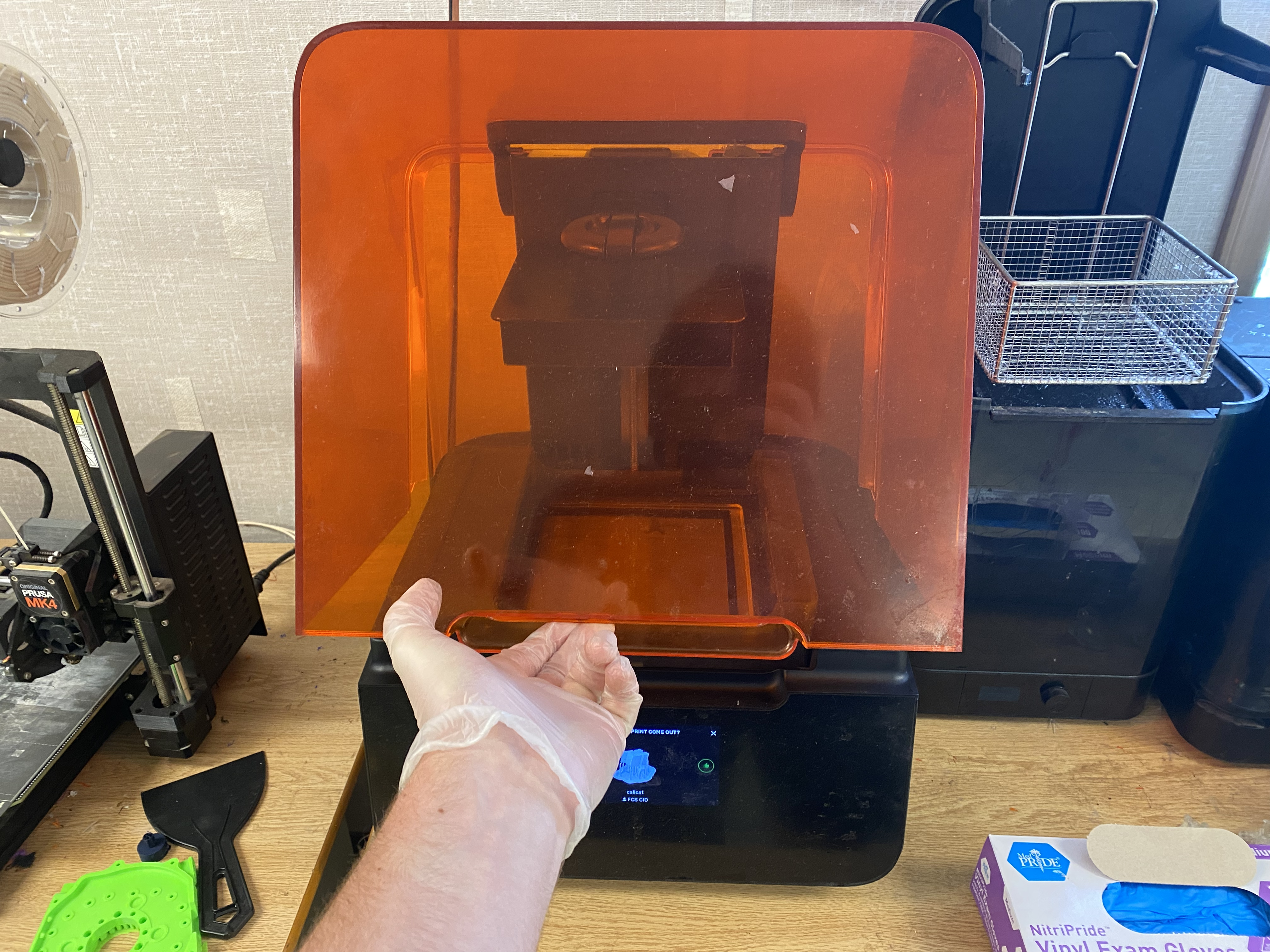
Then open the casing around the printer by pulling up on the handle.
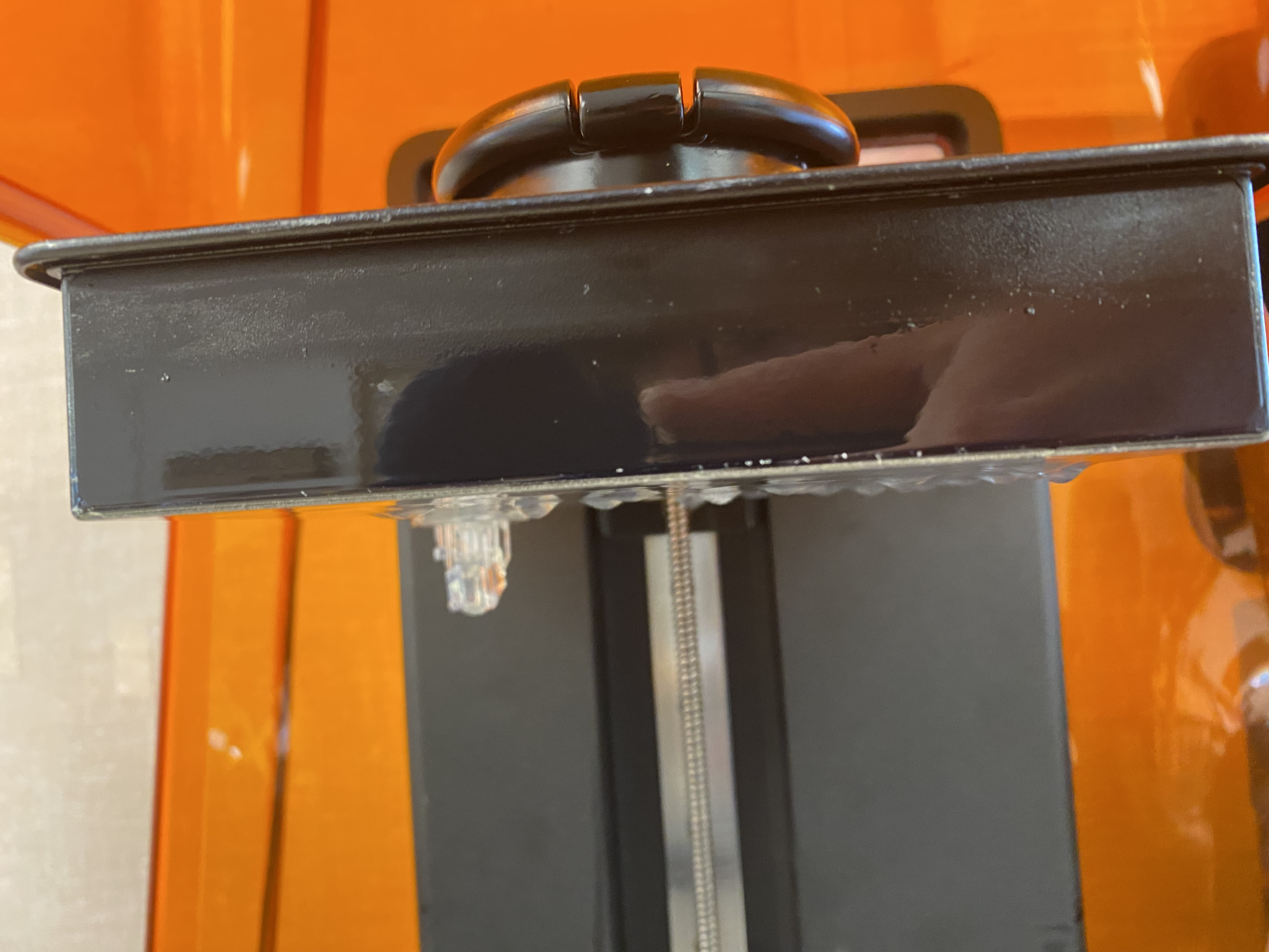
Inside, you will see your print attached upside-down to the print bed, and a mechanism holding the bed.
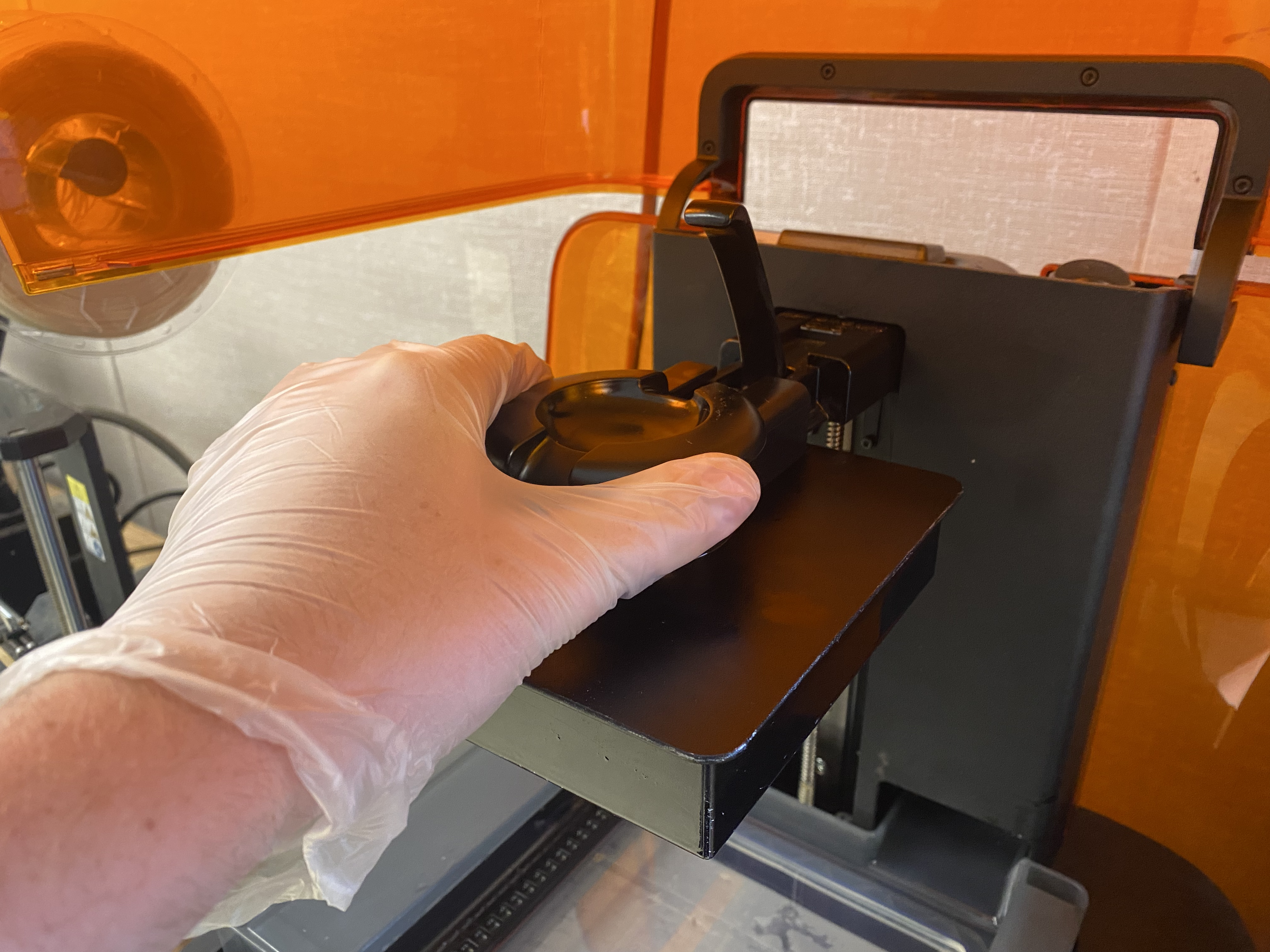
Unhook the latch holding the bed on and remove the print bed.
From there, get a scraper and carefully use it to pry the print off.
 .
.
Once all of your pieces are detached from the bed, proceed to the Washing and Baking section.
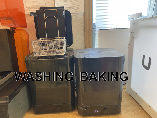
These steps will use the two black machines next to the Formlabs printer.
 with labels.
First, take your pieces and place them in the washing basin.
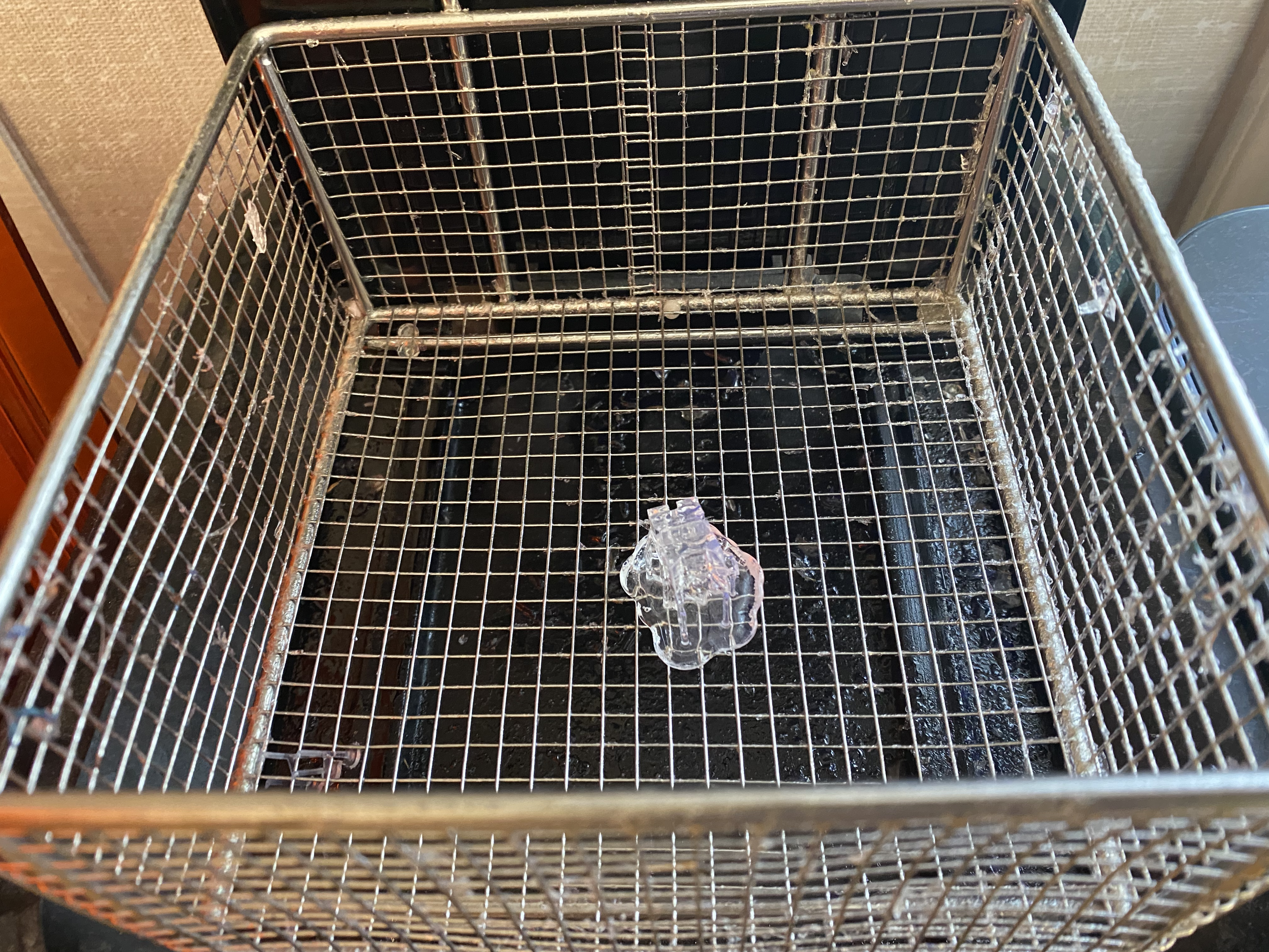
Click the knob to power the machine on, and then click it again to start the washing. You can change the settings with the dial but they will be set up for washing for you.
 .
.
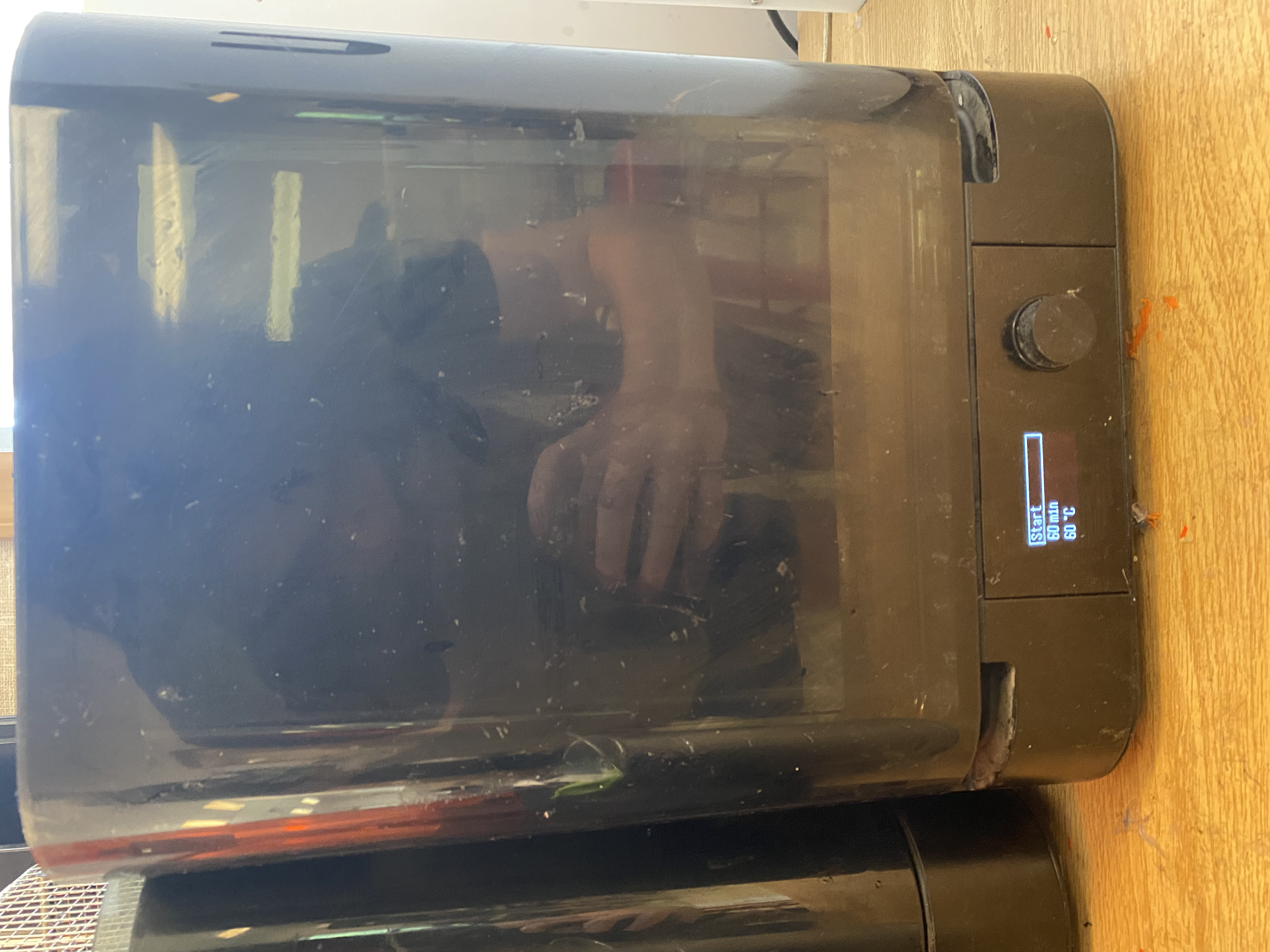
Once your pieces are done washing, you can take them out and move them into the second black box, to bake them.
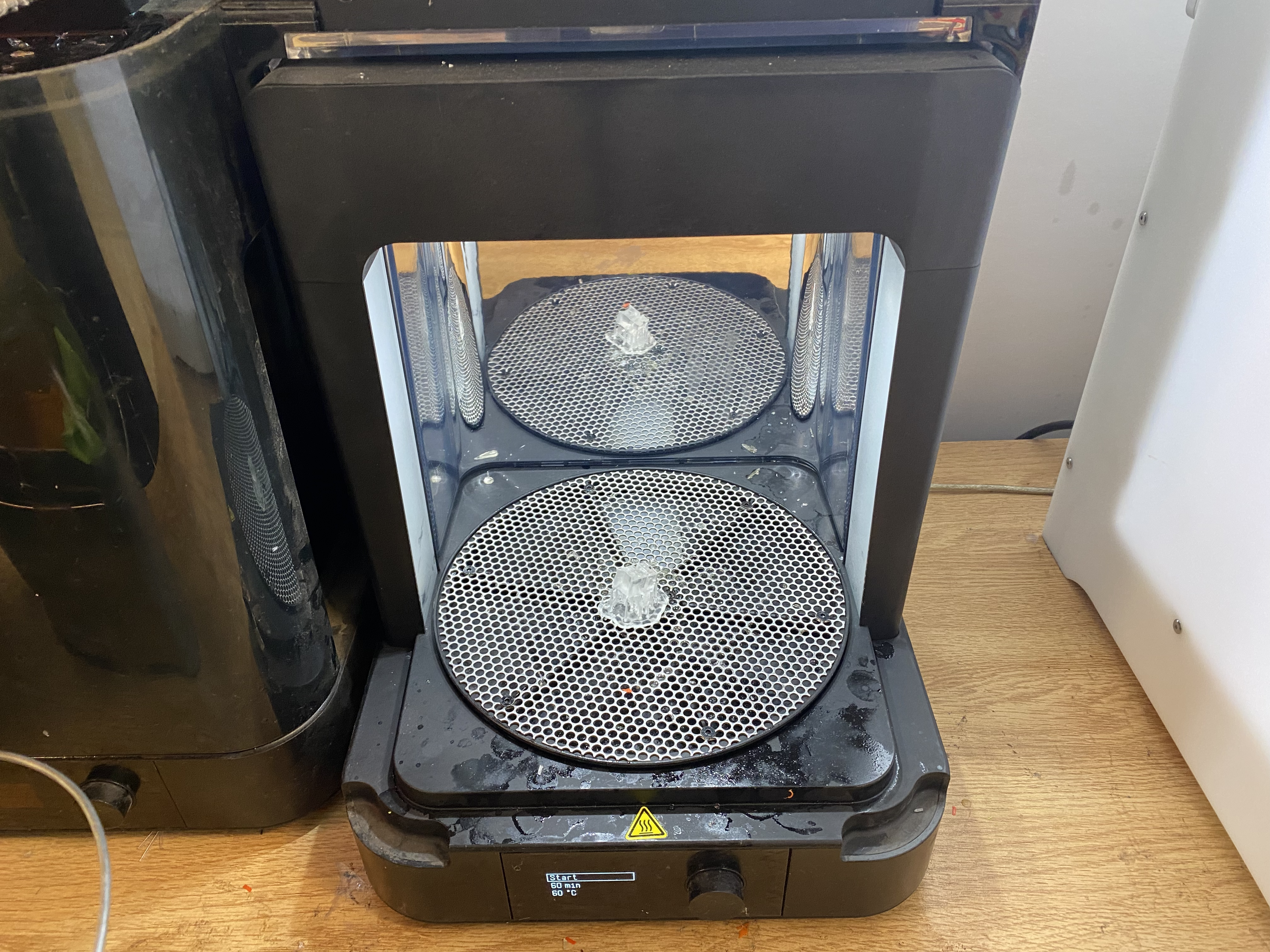
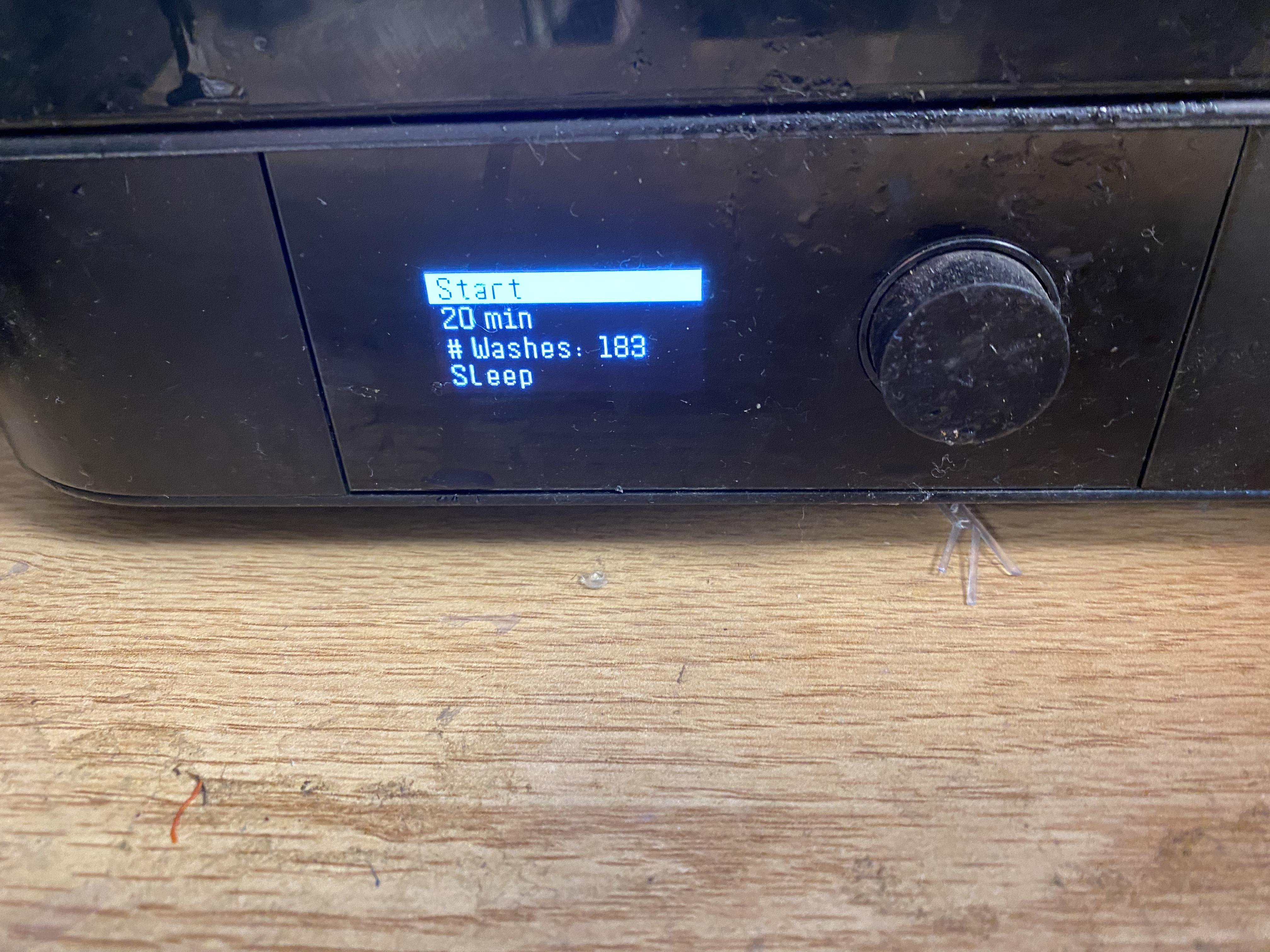
Place your pieces inside, close the lid, and click the knob once to activate the machine.
 .
.
The menu that pops up will show options for time and temperature. Use the guide on the wall to select the correct settings for your material, however 30 minutes at 60 degrees will work for the common resins that the printer will have loaded.
When the baking process is done, the print is complete!
Please do not attempt to change resin yourself. Get help from a trained adult if you need a different resin type.
The ultimaker is the biggest printer here in the CID and has the biggest build volume. It is also in my opinion the easiest to use. These guides are used to print with this printer:
To upload files to the Ultimaker first get the stl, obj, or other 3D file type and open it with UltiMaker Cura either through opening through File Explorer or dragging the file into the UltiMaker Cura application.

Once the file loads in, you can move it around the buildplate and change it to your likings, or upload more files by dragging them into the application window.
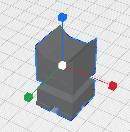
To move the print around the print bed, first click the item you wish to move, then click the ( ) icon and you will see three arrows pop up around your shape.
Once that happens you can either move it on the main axis by dragging those arrows, or just grab and drag the object to wherever you want it.
You can also set it’s exact position with the menu that appears next to the (
) icon.
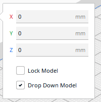
There you will also see two checkboxes, Lock Model and Drop Down Model.
Lock Model makes it so the model cannot move other than by changing the numbers in the menu, dragging the model or arrows will no longer move it .
Drop Down Model makes it so the model automatically moves its lowest point to be touching the print bed, and it cannot be moved upwards, but can still be moved downwards. Keep in mind that anything shown below the print bed will not be printed.
It is recommended to keep the Lock Model unselected and Drop Down Model selected.
To scale your object, select the object, then select the ( ) icon, and three lines with boxes will appear.
You can grab any of the three to stretch the object in the direction of that line, or instead grab the central box to stretch in all directions equally.
Again a menu will pop up with certain options. The text boxes allow you to set the length, width, or height of the object by measured size or percentage of the original model.
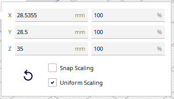
There you will also see two checkboxes, Snap Scaling and Uniform Scaling as well as a rewind icon.
Snap Scaling makes it so the object will snap between set sizes.
Uniform Scaling makes it so all the axes will scale uniformly, meaning any change to one axis will be matched in the other two to keep the proportions of the object the same.
The rewind icon will set the object to its original dimensions.
It is recommended to keep the Snap Scaling unselected and Uniform Scaling selected unless you intentionally want an of proportion model.
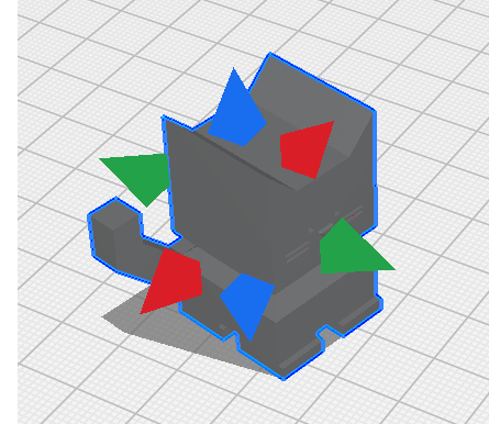
To scale your object, select the object, then select the ( ) icon, and three rings will appear.
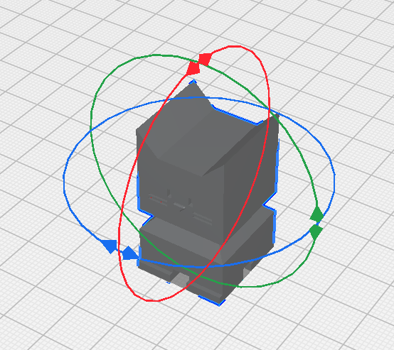
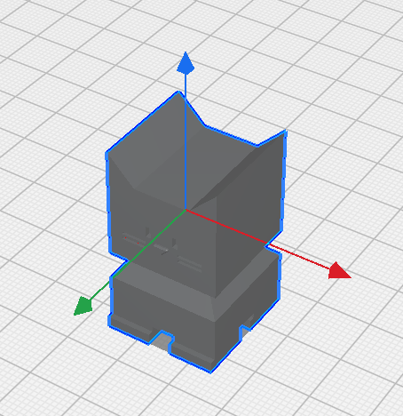
You can grab these rings and rotate them to rotate the object how you would like it to print. Keep in mind where the back of the bed is, signified by the lip where it is written Ultimaker S5.
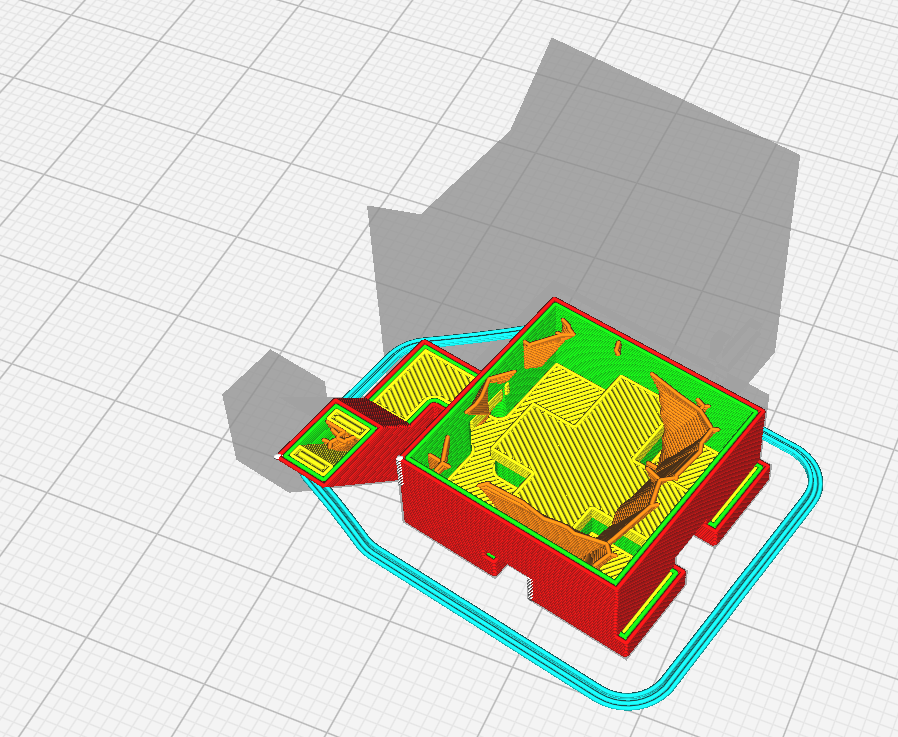
It is recommended to rotate the object so that the least amount of overhang is achieved:
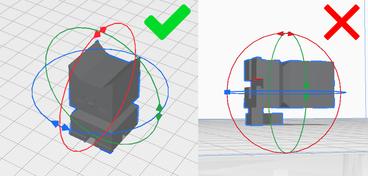
And the maximum amount of the print is touching the build plate, shown by the light blue highlight:
Again a menu with certain options will also appear next to the (
) icon.
The rewind icon will return the object to its original orientation.
The ( ) icon will rotate the model as little as possible to ensure a flat surface is laying against the print bed.
The ( ) icon will allow you to click on a face of the print and the program will lay it flat against the print bed. This feature is somewhat inconsistent so it may take a few tries to correctly align it.
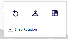
Snap Rotation makes it so the print will only rotate in multiples of 15 degrees.
It is recommended to keep Snap Rotation selected unless a particular angle is needed.
When you select the ( ) icon, 6 arrows will appear.
Clicking any of these arrows will mirror the object as if there was a mirror that the arrow was pointed directly into.
When you click the ( ) icon, a section will open that allows you to change how the object prints.
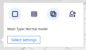
The first icon is the default, and will follow the print settings that you set.
The second prints as if is is support for a different model, which will follow the support settings that you set.
The third will deal with overlapping objects, which is much more complicated, and a full description of the options can be found here: https://support.makerbot.com/s/article/1667417981430.
The last will remove all supports in the volume of the object, but will not print the object itself.
The ( ) icon will block support in a cubic area, similar to the last option of the last tool.
To use this, click the model you want to remove supports from, click the (
) icon, and then click where you want the blocker. You can then edit the blocker as if it was any other object, using the tools above. The print will not generate any supports in the area of this block.
The Ultimaker can print two materials in the same print, simply click the object and select which of the two extruders you wish to print from.
Once you are happy with the object’s placement, move to the Printer Settings section.
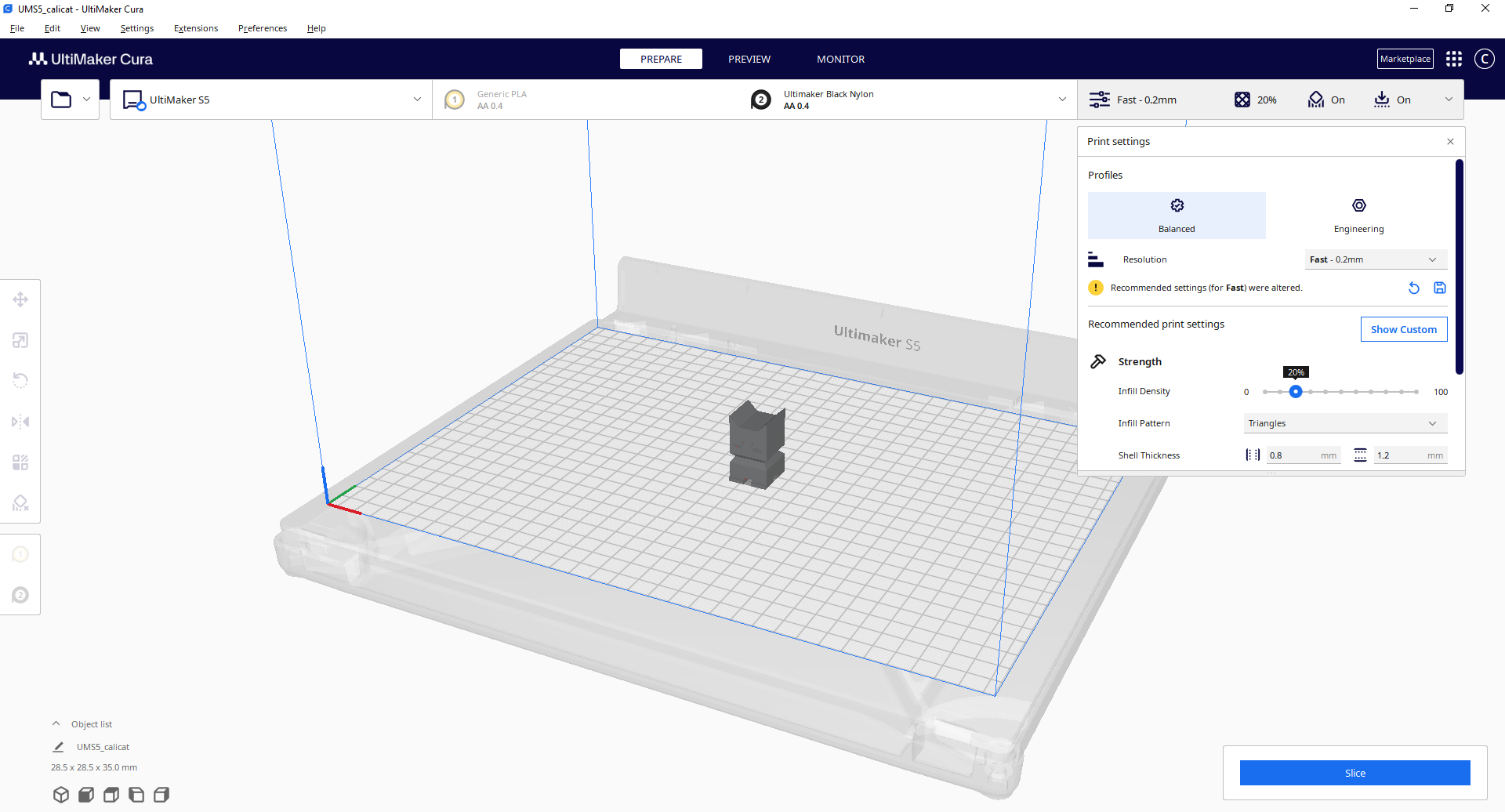
Once you have your object oriented as desired, move to the print settings menu.
There you will see lots of options, which I will briefly review here.
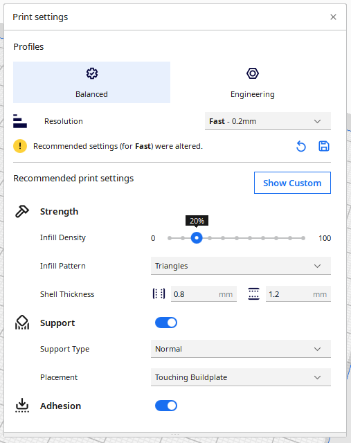
Firstly you will see a list of Profiles. These are the easiest way to select your settings.
Balanced strikes a balance of productivity, quality, strength, and accuracy. Use this for general projects.
Visual prioritizes the outwards appearance to optimize visual properties. Use this for projects that need to look good.
Engineering prioritizes accurate tolerances, and mechanical strength. Use this for projects will moving parts or that need to be stronger.
Draft is for models that are prototypes or not particularly valuable. Use this for testing and quick prints.
Resolution will change the thickness of every layer. The bigger each layer is the faster the model will print, but the worse it will look and function. It’s recommended to use Fine for good visual quality or Fast for speed and basic functionality.
Below it may say “Recommended settings for _____ were altered”. Clicking the rewind icon will reset to recommended settings and the floppy disk icon will save the current settings as a new preset.
This slider will allow you to dictate how much of the interior of the print is filled in, with 0 meaning no fill, and 100 meaning completely full.
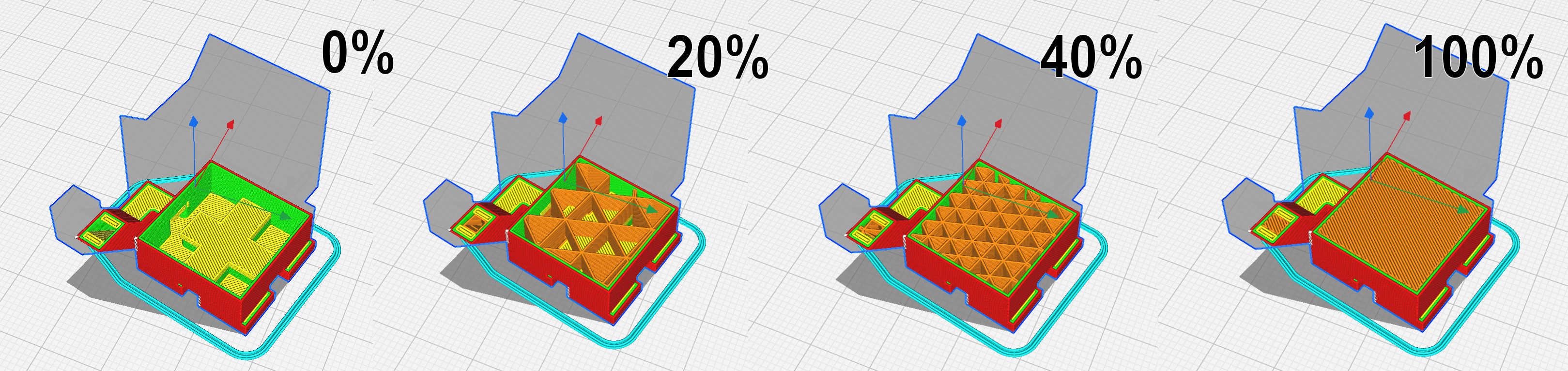
anything down to 10% will be self supporting enough, although 20% is recommended for nearly every print. 70% is the absolute maximum you need to go for a high strength print, however this should only be used if extreme strength is needed.
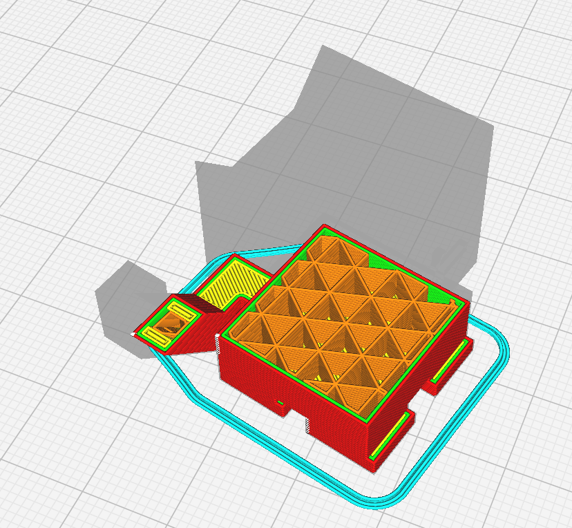
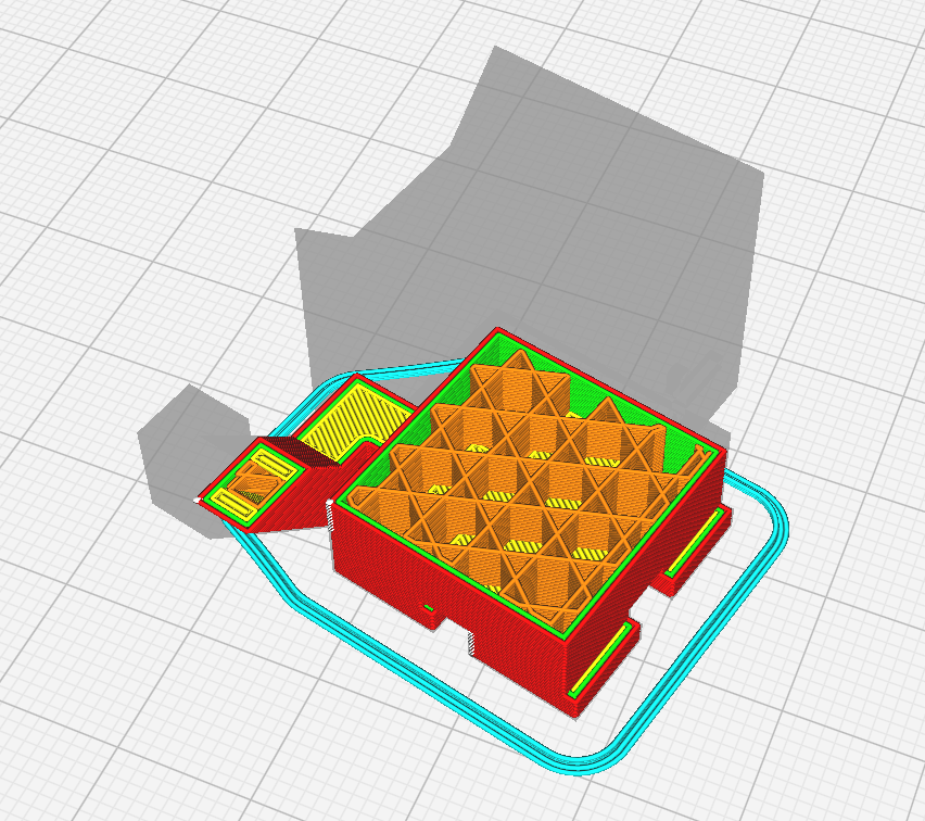
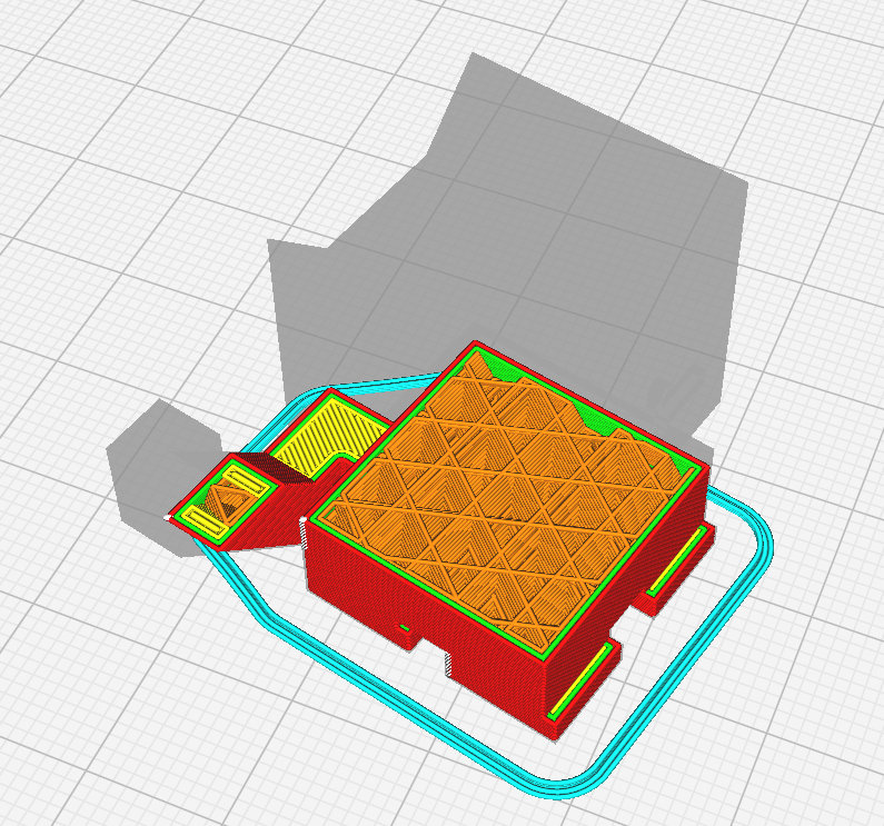
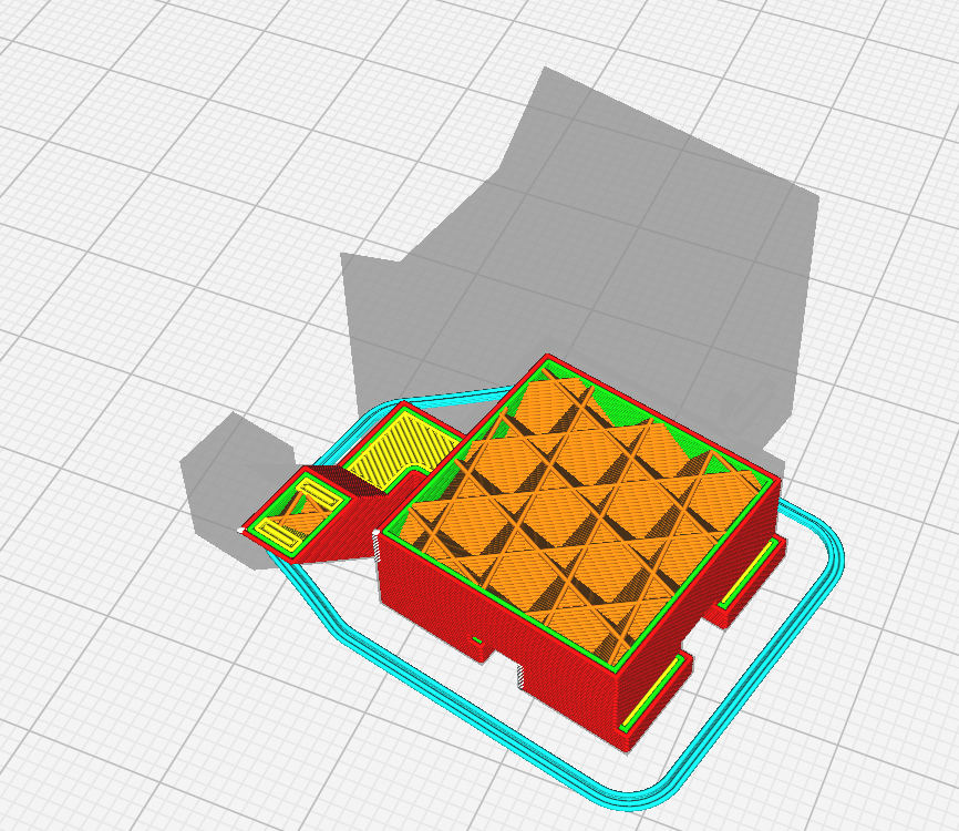
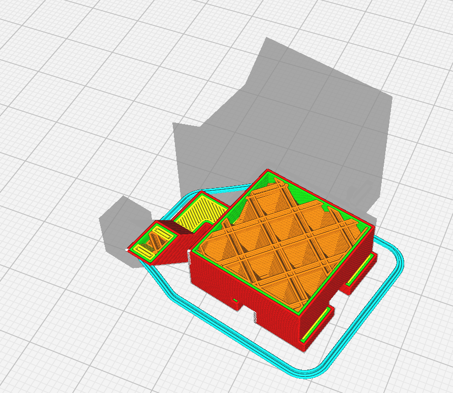
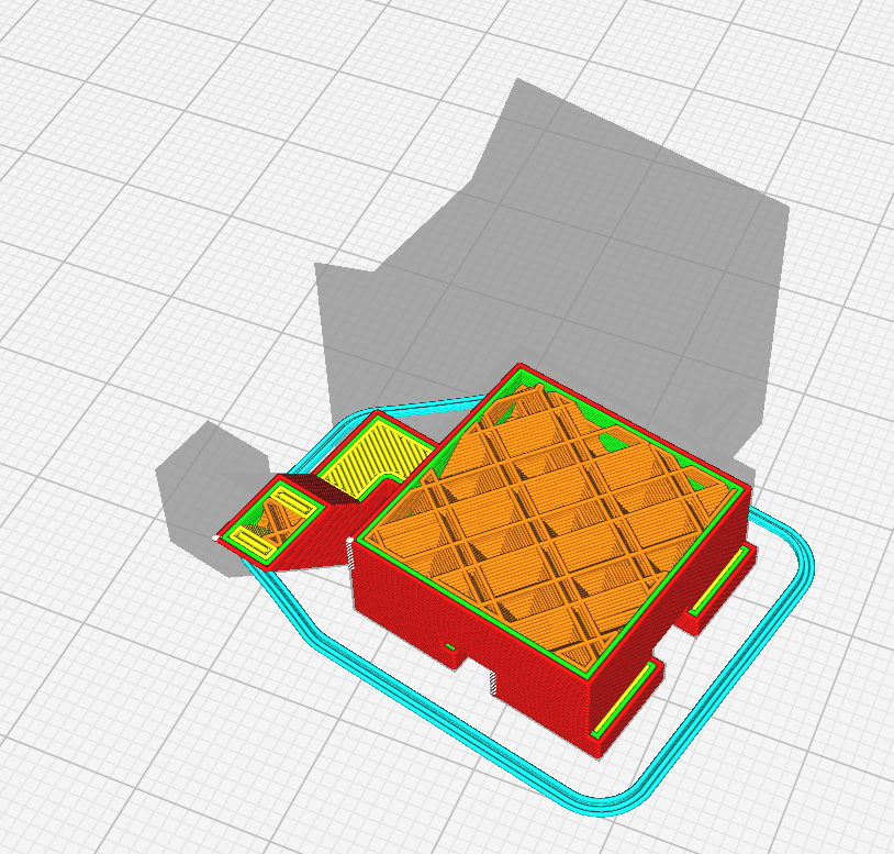
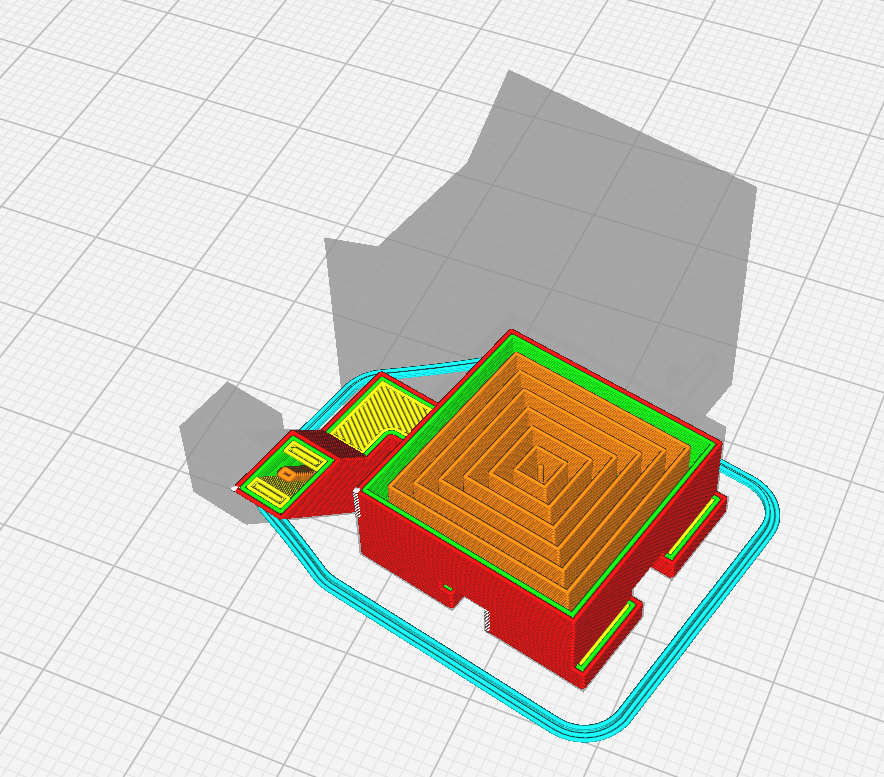
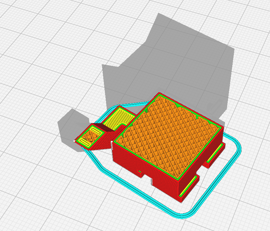
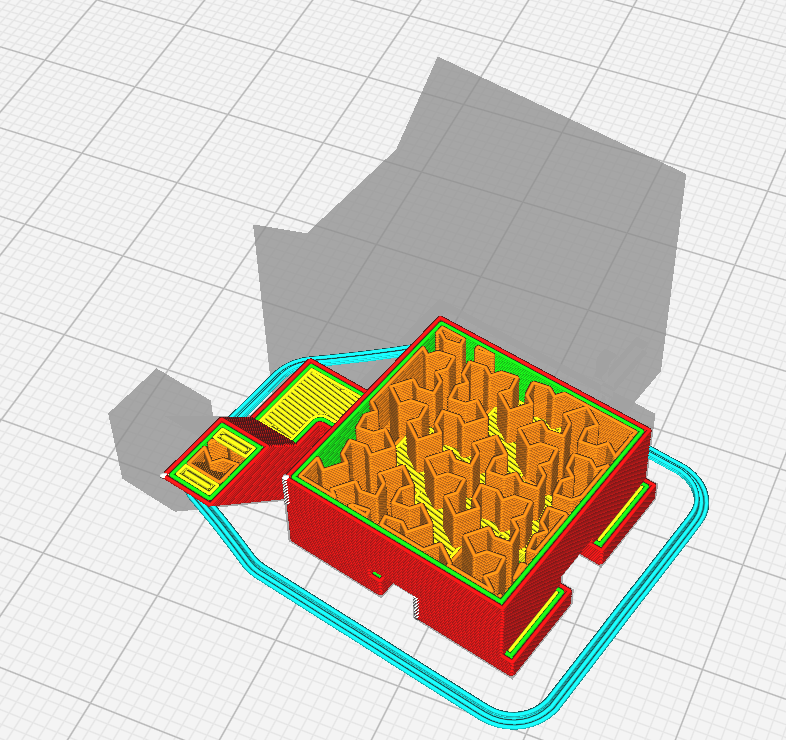
This allows for a selection of how the infill will be created, with options shown below:
Grid
 Lines
Lines
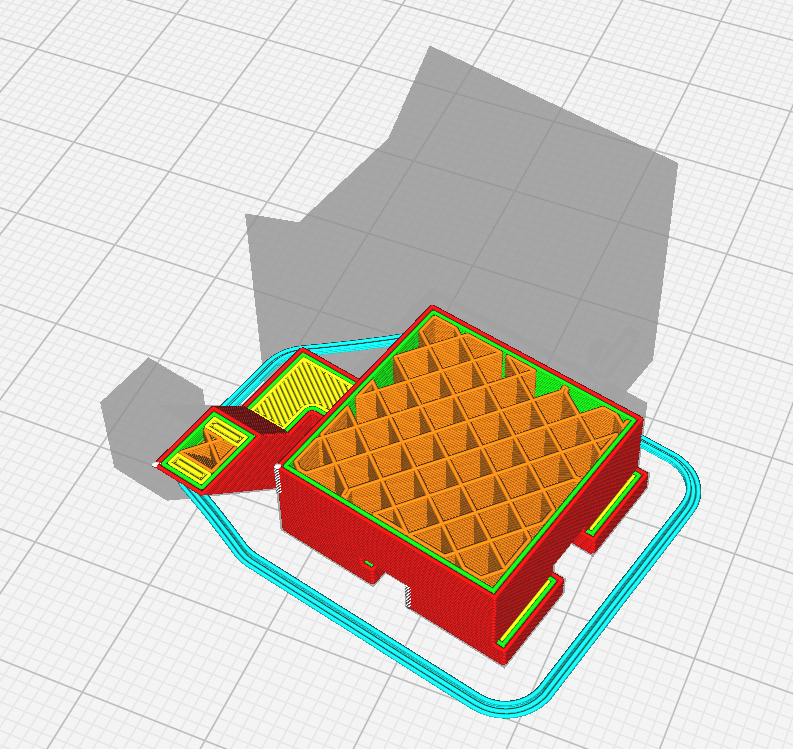
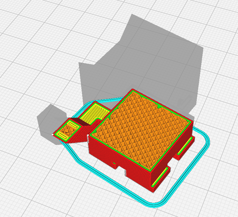 Triangles
 Trihexagon
 Cubic
Cubic
 Cubic Subdivision
 Octet
Octet
 Quarter Cubic
 Concentric
 Zig Zag
 Cross
Cross
 Cross 3d
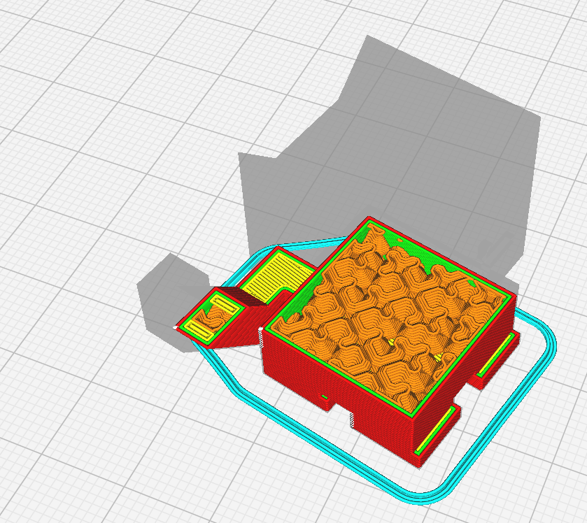 Gyroid
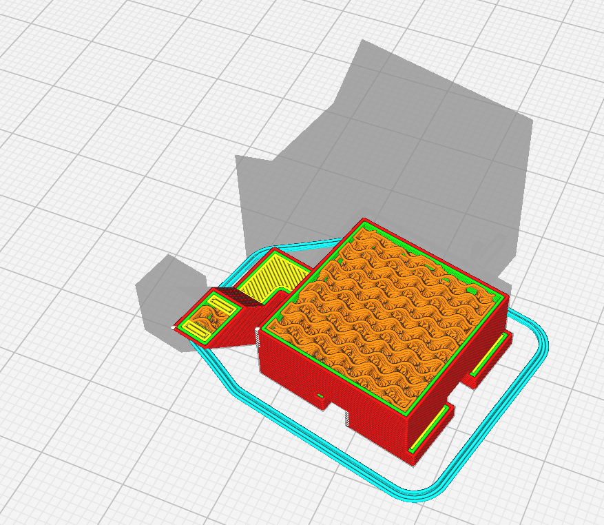 Lightning
Triangles is the recommended setting but this choice has little effect on the overall print.
This lets you set the thickness of the outer shells of the print, with the first box designating the side walls, and the second designating the top and bottom.
Supports are how the printer helps overhangs print, as the printer must always work from bottom to top and cannot print without a surface to print on. Support can be selected and deselected, but is recommended to use whenever there are overhangs or floating objects in your print.
This box allows for two choices, Normal and Tree.
Normal creates sheets of support under your print, connected at top and bottom:
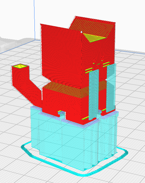
Tree creates branching circular structures to support overhangs in the model:
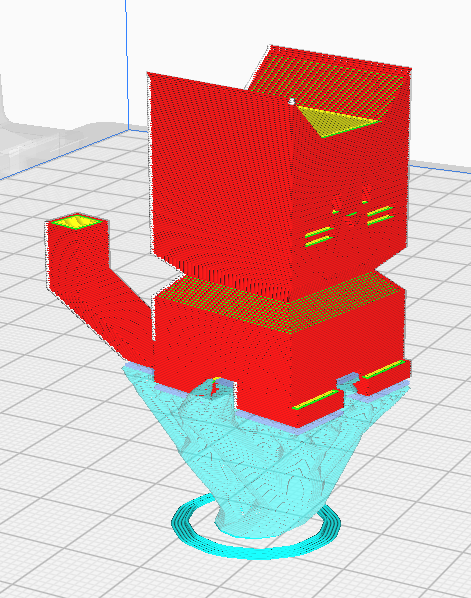
Normal is the recommended setting unless it creates particularly hard to remove sections with print trapped between support on all sides.
Placement designates where supports generate, and gives two options, Everywhere and Touching Buildplate.
Everywhere means any overhang will be supported, no matter where on the print it is.
Touching Buildplate will only support overhangs over the buildplate, and overhangs that have other bits of object below will not generate support.
It is recommended to use Everywhere when overhangs are present.
Adhesion helps prints stick to the print bed and avoid shifting and warping off of the bed. It is recommended to keep this setting selected for any print.
Many other specific settings can be tuned by clicking Show Custom however there are far too many to cover in this guide, so look to a more specific guide on the Cura Slicer for information on that.
Once you have your preferred settings set, move to the Slicing Files section.
Once you have set up your print how you want it, press the Slice button in the bottom right.
Once you do this, you will see a new tab appear, Preview. This allows you to look at the exact printing path of the printer.
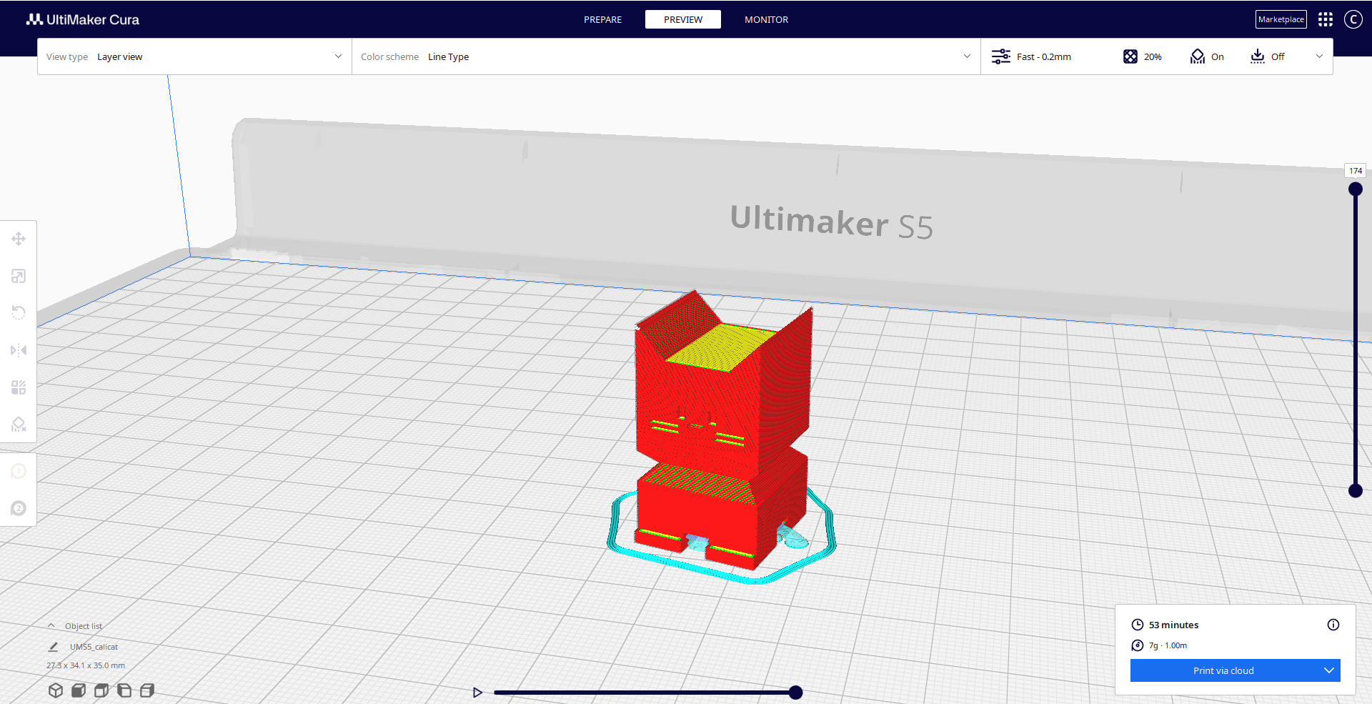
Here you can use the slider on the right to move up and down the layers, showing each layer path individually, and then use the bottom slider to watch the exact movement path for that layer.
Once you have done this, move to the Transferring to printer section.
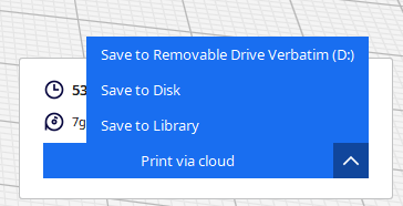
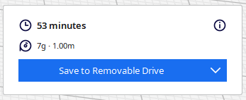
Once you have your gcode file, take the USB drive out of the printer and plug it into the computer. You can ignore any windows that pop up after doing this. Navigate back to UltiMaker Cura and look to the bottom right. If the button says Save To Removable Drive click it. If not, click the up arrow, then click Save To Removable Drive to make the button read Save To Removable Drive, then click the button.
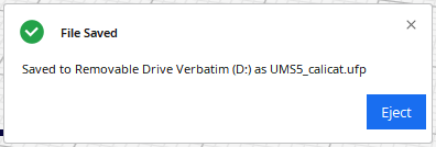
Once you do this a saving progress bar will appear, and then a box that says File saved. You can then press the Eject button that appears there. Once the box reads Drive Successfully Ejected you can remove the USB stick.
Finally plug the drive back into the printer. Once you have done this move to the Printing section.
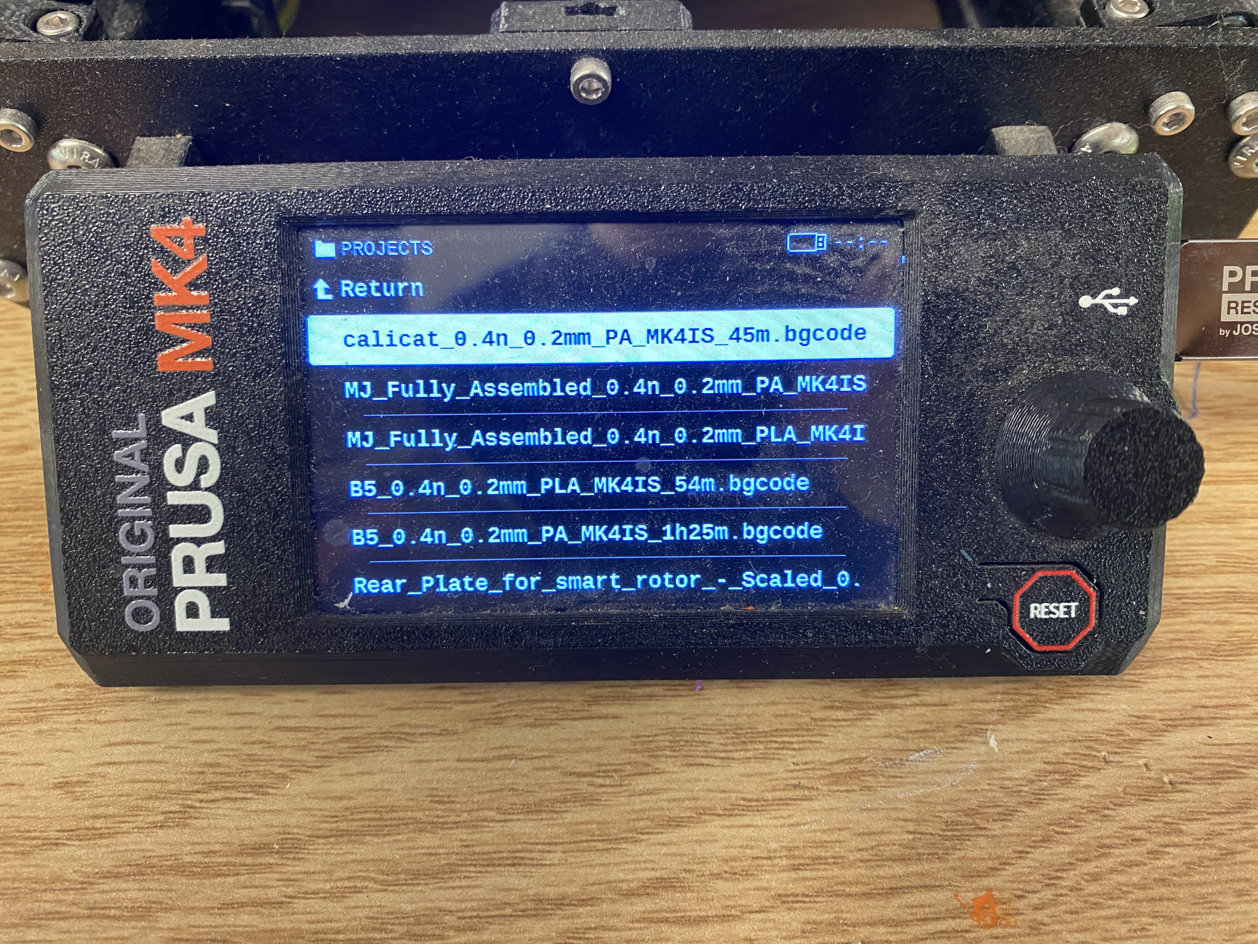
Once you plug the USB into the printer, you should be greeted with this image.
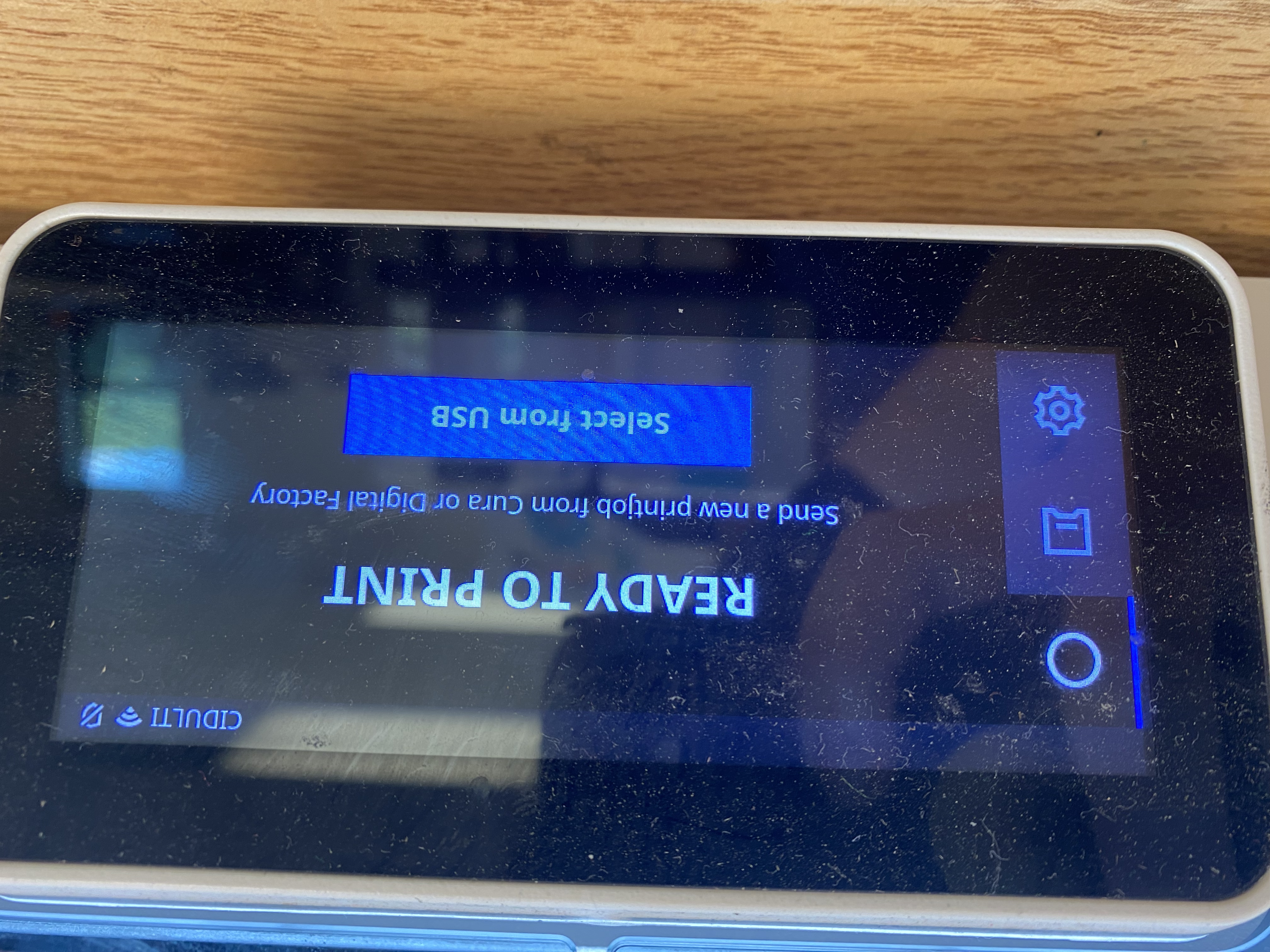
To print, hit the Print from USB button, then scroll until you see the file you wish to print. Press the file name and another menu will appear.
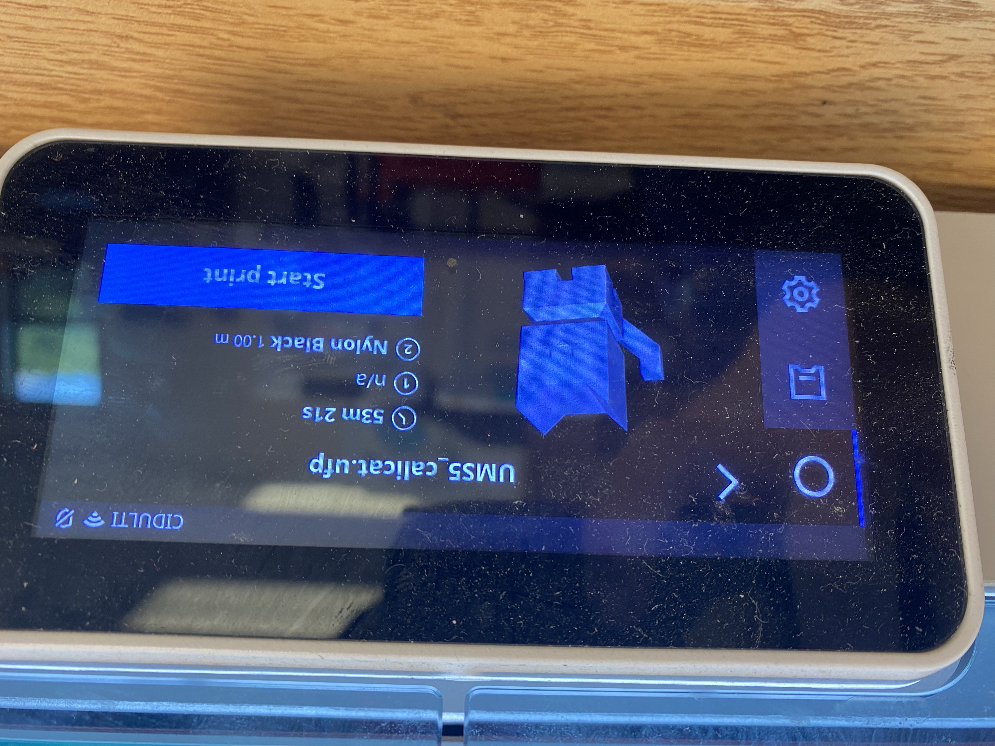
Check that the time, and two filament types match what you expect, and then press start print. Your file should then print! If the filament types do not match what is in the printer, go to the Changing Filament Section. If any other issues arise go to the Troubleshooting section.
Most errors with the UltiMaker will create an error message accompanied by the QR code. If this happens scan the QR code to find out how to fix the error.
The most common errors occur when:
The white silicone cover is not on the print heads: To fix this reinsert the silicone cover.
The printer thinks it does not have filament loaded but does: To fix hit the OK button and hit resume when it returns to the printing screen, the printer will figure out that it does in fact have filament.
The Prusa Mark 4s are arguably the best printers we have, with a great mix of speed and accuracy, and they can be run at up to 500% speed with a good level of accuracy. The guides to print with these are below:
To upload files to the Prusa Printers first get the stl, obj, or other 3D file type and open it with PrusaSlicer either through opening through File Explorer or dragging the file into the PrusaSlicer application, or clicking the ( ) icon and selecting the file.
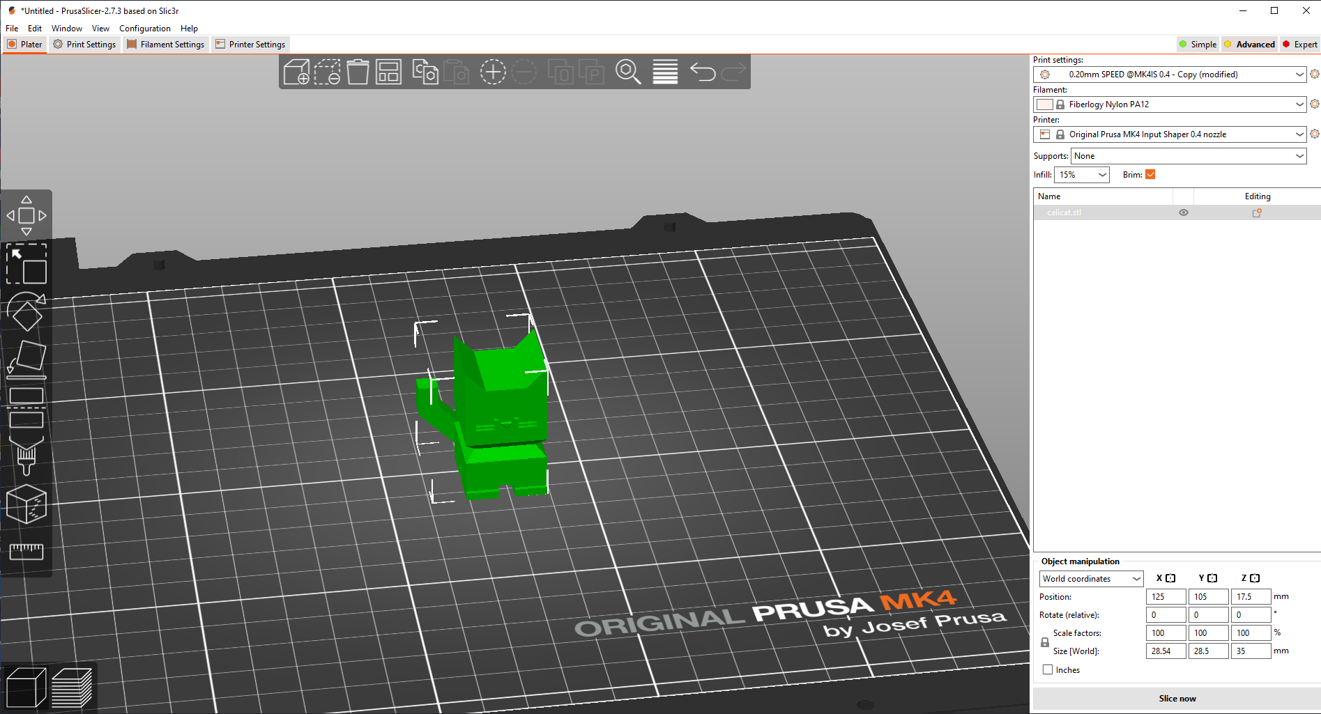
Once the file loads in, you can move it around the buildplate and change it to your likings, or upload more files by dragging them into the application window.
In the top menu you will see a list of options.
( ) will allow you to add a file from file explorer
( ) will delete the current selected object
( ) will clear the buildplate of all objects
( ) will arrange the models on the buildplate
( ) will copy the selected object
( ) will paste from the clipboard
( ) will add a copy of that object
( ) will remove a copy of that object
( ) will split a separated object into multiple objects
( ) will split a separated object into multiple parts
( ) will let you search features
( ) will bring up the
 variable layer height menu which is beyond the scope of this guide and should not be used without a more comprehensive understanding of the printers.
( ) undoes the last action
( ) redoes the last undo
To move the print around the print bed, first click the item you wish to move, then either drag your shape to its intended position, or click the ( ) icon and you will see three arrows pop up around your shape.
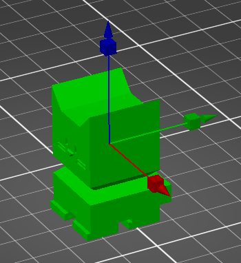
Once that happens you can either move it on the main axis by dragging those arrows, or just grab and drag the object to wherever you want it.
You can also set its exact position with the menu on the bottom right of the screen.
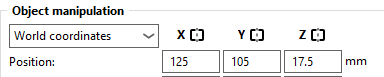
There you will also see a menu with two options World Coordinates and Object Coordinates.
World Coordinates lets you set position relative to the bed, with 0,0 being at the bottom left corner.
Object Coordinates lets you shift the object from its current position and will move it as far as you put in. You can also switch to measuring in inches by checking the inches box.
To scale your object, select the object, then select the ( ) icon, and three lines with boxes will appear, as well as a few orange boxes in a square around it.
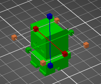
You can grab any of the three to stretch the object in the direction of that line, or instead grab one of the orange boxes to stretch in all directions equally.
You can also set its exact scale with the menu on the bottom right of the screen.
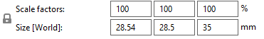
Scale Factors allows you to set the scale relative to the original object.
Size \[World\] allows you to set the numeric size along all three axis. You can also switch to measuring in inches by checking the inches box.
If the lock icon is closed, the object will retain it’s original proportions and scale axis equally. If it is open you can manipulate the three separately.
The rewind icon will set the object to it’s original dimensions.
To rotate your object, select the object, then select the ( ) icon, and three rings will appear.
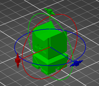
You can grab these rings and rotate them to rotate the object how you would like it to print. Keep in mind where the front of the bed is, signified by where it is written Prusa MK4.
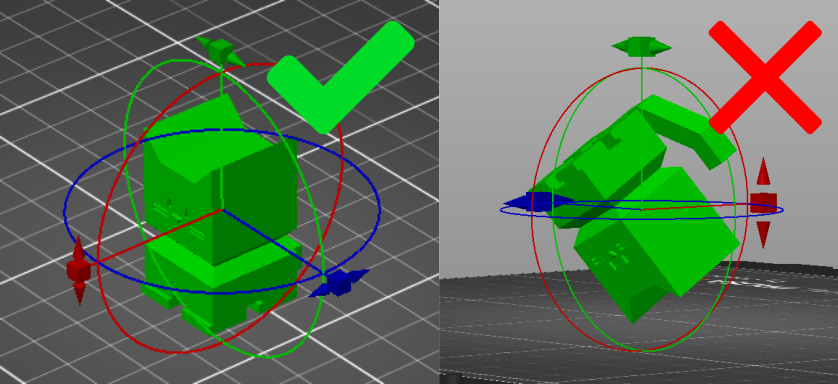
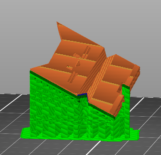
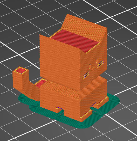
It is recommended to rotate the object so that the least amount of overhang is achieved:

And the maximum amount of the print is touching the build plate:
You can also set its exact rotation with the menu on the bottom right of the screen.

Putting numbers in the text boxes will rotate the object in the direction of the arrows that appear as many degrees as you insert in the box.
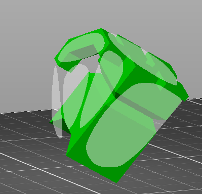
You can also click the ( ) icon and your object will show white planes. Clicking one of these will orient the object so that the selected plane is touching the buildplate.
To cut your object in 2 pieces, hit the ( ) icon, and a menu will appear, as well as the cutting plane.
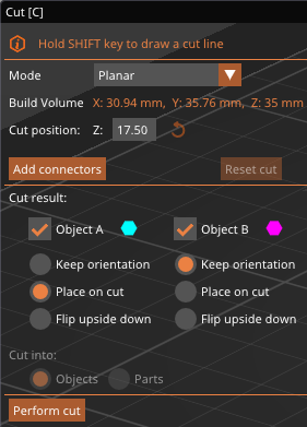
In the menu you will see a selection box labeled Mode. Inside there are two options, Planar and Dovetail.
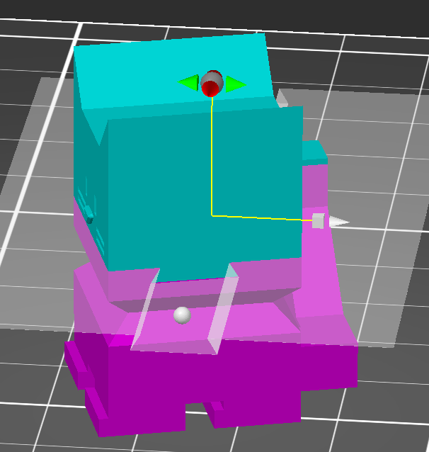
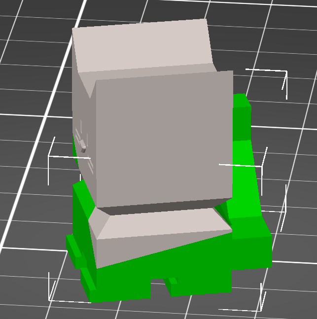
When you select planar, you should first select where you would like to cut the file. The plane will automatically appear and shade the two halves of the object different colors. To adjust this cut, you can either drag the red and green arrows to tilt the plane, or grab and drag the grey ball to move the plane.
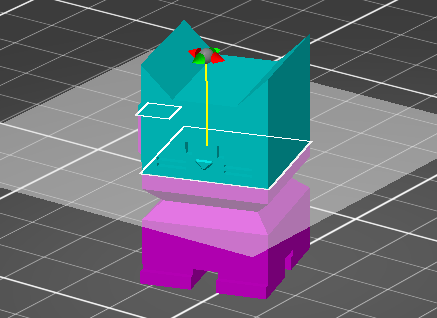
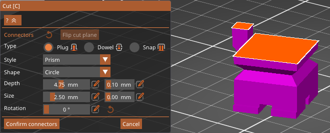
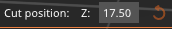
You can also set the height of the cut off of the buildplate automatically in the menu.
This will create a smooth cut into two pieces.
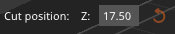
If you want to instead have a more secure way of joining these pieces after you cut, press the Add Connectors button.
From there it will hide one of the two halves, and allow you to place connectors. You will see 3 options for the type of connector, Plug, Dowel, and Snap.
Plug creates a small protrusion from one side, and a matching hole in the other. You can select whether you would like a prism or frustum shape:
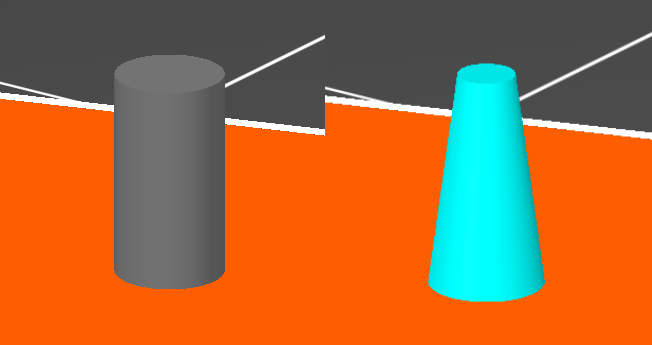
As well as what shape you would like it to be, triangle, square, hexagon, or circle:
Dowel creates holes in both halves of the print as well as a small dowel to join the two.
Again you can choose the shape of the dowel, triangle, square, hexagon, or circle:
Snap creates a small mechanism which will snap into a hole in the other piece.
For all of these options, you can change the depth out of or into the piece, the horizontal size of the peg, and the rotation around its center.
For the snap you can alter the bulge of the top section and space between connectors. Hitting the rewind icon will pu tit back to default settings.
Once you are happy with the settings, you can click anywhere on the orange surface to place the connector where you click.
Hit confirm connectors once you are happy with the connector position and settings or cancel to return to the cut menu.
Dovetail will create a unique joint between the two pieces, where one will be able to slide into the other.
The plane will automatically appear and shade the two halves of the object different colors. To adjust this cut, you can either drag the red and green arrows to tilt the plane, grab and drag the white ball to rotate the groove, or grab and drag the grey ball or cube to move the plane.
You can also set the height of the cut off of the buildplate automatically in the menu.
From there you can adjust the settings of the dovetail joint, with the sliders provided. Hitting the rewind icon on any slider will set that slider back to it’s default position.
Below the other settings, you will see a section named Cut Result. There you will see a column for each half of the cut. If the check box is selected the cut will generate that pice and not discard it.
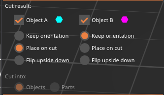
You can then select how to place the object once it cuts. Keep Orientation will keep the object as it is before that cut. Place On Cut will lay the object along the plane of the cut. Flip Upside Down will invert the object.
If you have selected planar and not added connectors, you can at the bottom select to cut into parts instead of objects, which will leave the two sides connected but allow them to have their settings edited separately with the left parts menu.
If you press the ( ) icon you can add supports in specific spots by “painting” with your mouse. Click and drag to add supports where you drag, and right click and drag to block supports in the certain spots you “paint”.
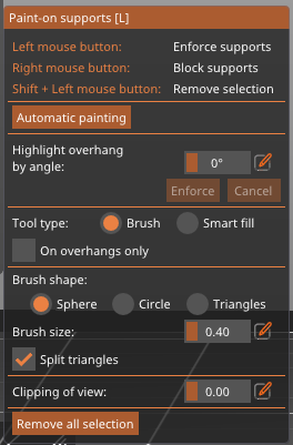
You can also automatically paint areas, edit where can be painted, and edit your “brush” shape in the menu below.
If you press the ( ) icon you can control where each layer of the print starts and ends, creating a small slightly visible seam.
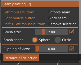
Clicking and dragging will force the printer to place a seam there, and right clicking and dragging will stop seams in that area.
You can also change the shape of your brush and view options in the menu that appears.
To measure your object, select the object, then select the ( ) icon. You can then click individual faces, edges, and points to measure the distance, angle, and areas of the parts selected.
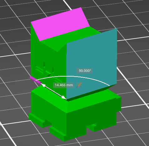
When you measure a length, a ( ) icon will appear, and allow you to change the length highlighted and scale the rest of the model to enforce that length.
In the menu you can either hit the Restart Selection button to clear your selection, or click the ( ) icon next to the measures to copy the numbers there.
Once you are happy with the object’s placement, move to the Printer Settings section.
Once you are satified with the object placement, move to the right menu.
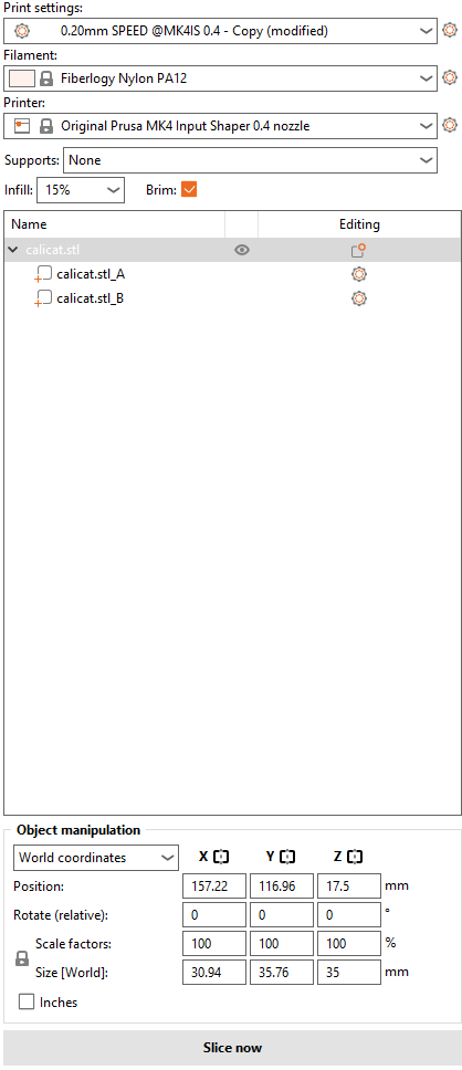
Here you will see a list of settings for layer heights:
0.1 mm will be the most precise setting, good for visual detail or mechanical functionality.
0.15 mm has both SPEED and STRUCTURAL options, choose SPEED for a faster print, or STRUCTURAL for a sturdier print.
0.2 mm has the same options, but both will be faster but lower quality than their 0.15 mm counterparts.
Here you can select the type of filament to be printed. Make sure this matches what is loaded in the printer before printing.
Here you select which printer to use. Select Original Prusa MK4 Input Shaper 0.4 nozzle.
Supports are how the printer helps overhangs print, as the printer must always work from bottom to top and cannot print without a surface to print on. Support can be selected and deselected, but is recommended to use whenever there are overhangs or floating objects in your print.
The options in the dropdown designate where supports generate, and gives 4 options, None, Support on Buildplate Only, For Support Enforcers Only, and Everywhere.
None will not create any supports.
Support on Buildplate Only will only support overhangs over the buildplate, and overhangs that have other bits of object below will not generate support.
For Support Enforcers Only only puts supports in specified spots, either by you or the model itself.
Everywhere means any overhang will be supported, no matter where on the print it is.
It is recommended to use Everywhere when overhangs are present.
This will allow you to dictate how much of the interior of the print is filled in, with 0 meaning no fill, and 100 meaning completely full.
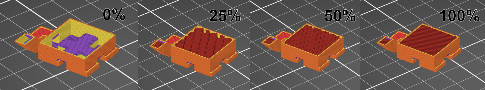
Anything down to 10% will be self supporting enough, although 20% is recommended for nearly every print. 70% is the absolute maximum you need to go for a high strength print, however this should only be used if extreme strength is needed.
The brim helps prints stick to the print bed and avoid shifting and warping off of the bed. It is recommended to keep this setting selected for any print.
In the part menu, you can select and change settings for specific parts by clicking the ( ) icon.
The full scope of this will not be covered on this website.
In the top left you will see tabs wil more settings. These can affect more specific things about the print and printer but that is only recommended to use if you are more comfortable with the printer and how it works.
Once your settings are as desired, move to the Slicing Files section.
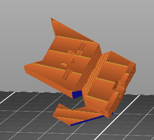
Once you have set up your print how you want it, press the Slice button in the bottom right.
insert 
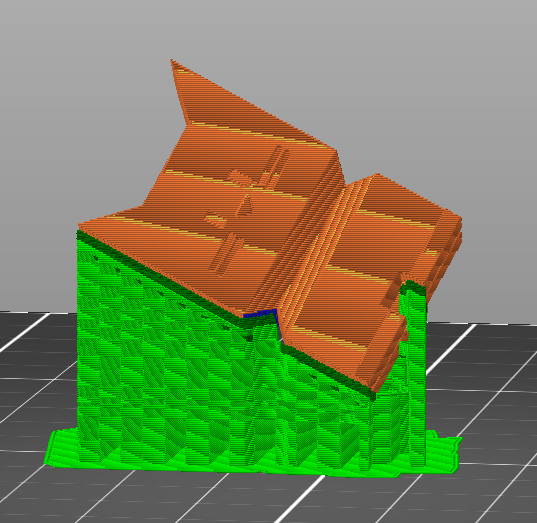
Once you do this, you will se a new tab appear, Preview. This allows you to look at the exact printing path of the printer.
insert 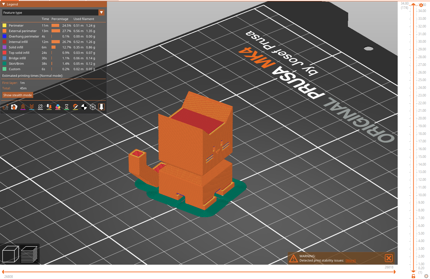
Here you can use the slider on the right to move up and down the layers, showing each layer path individually, and then use the bottom slider to watch the exact movement path for that layer.
You can add breaks, custom g-code, and filament swaps into your print from here, by sliding the slider on the right to where you want and either clicking the ( ) icon to add a color swap, or right clicking to choose between pause, custom g-code, and color swaps.
Pauses will stop the print and let you either add parts into the print or check the print, and resume when you press a button on the printer. Add custom g-code will have the printer run a set custom g-code file. Color swap will do the same as regular clicking.
If you choose to do a filament swap, make sure you are using the same type of filament.
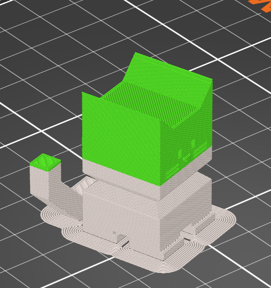
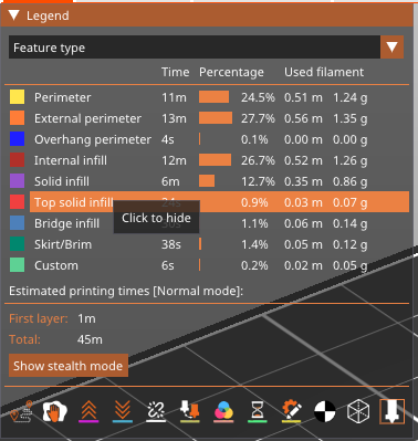
You can also see specific parts of the print broken down by type of print and shaded different colors, as well as a menu of options at the bottom. This lets you view more specific information about the print.
Once you have done this, move to the Transferring to Printer section.
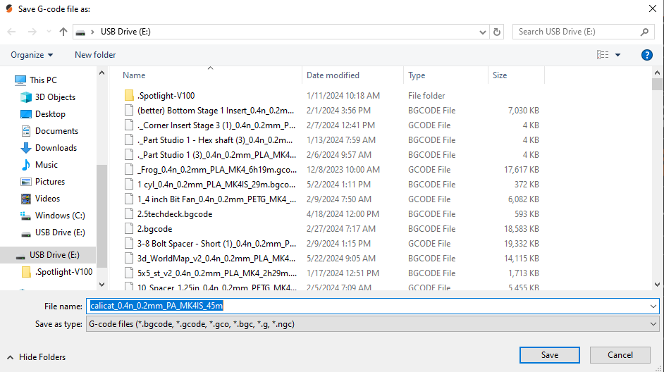
Once you have your gcode file, take the USB drive out of the printer and plug it into the computer. You can ignore any windows that pop up after doing this. Navigate back to PrusaSlicer and look to the bottom right. Click the ( ) icon and hit
 Save when the window appears.
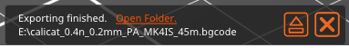
Wait until the box at the bottom reads Exporting Finished then hit the eject icon. It is safe to remove the USB once the box reads Successfully Unmounted.
Finally plug the drive back into the printer. Once you have done this move to the Printing section.
Once you load the USB drive back into the printer, if the file you wish to print was recently uploaded to the USB it will appear automatically.
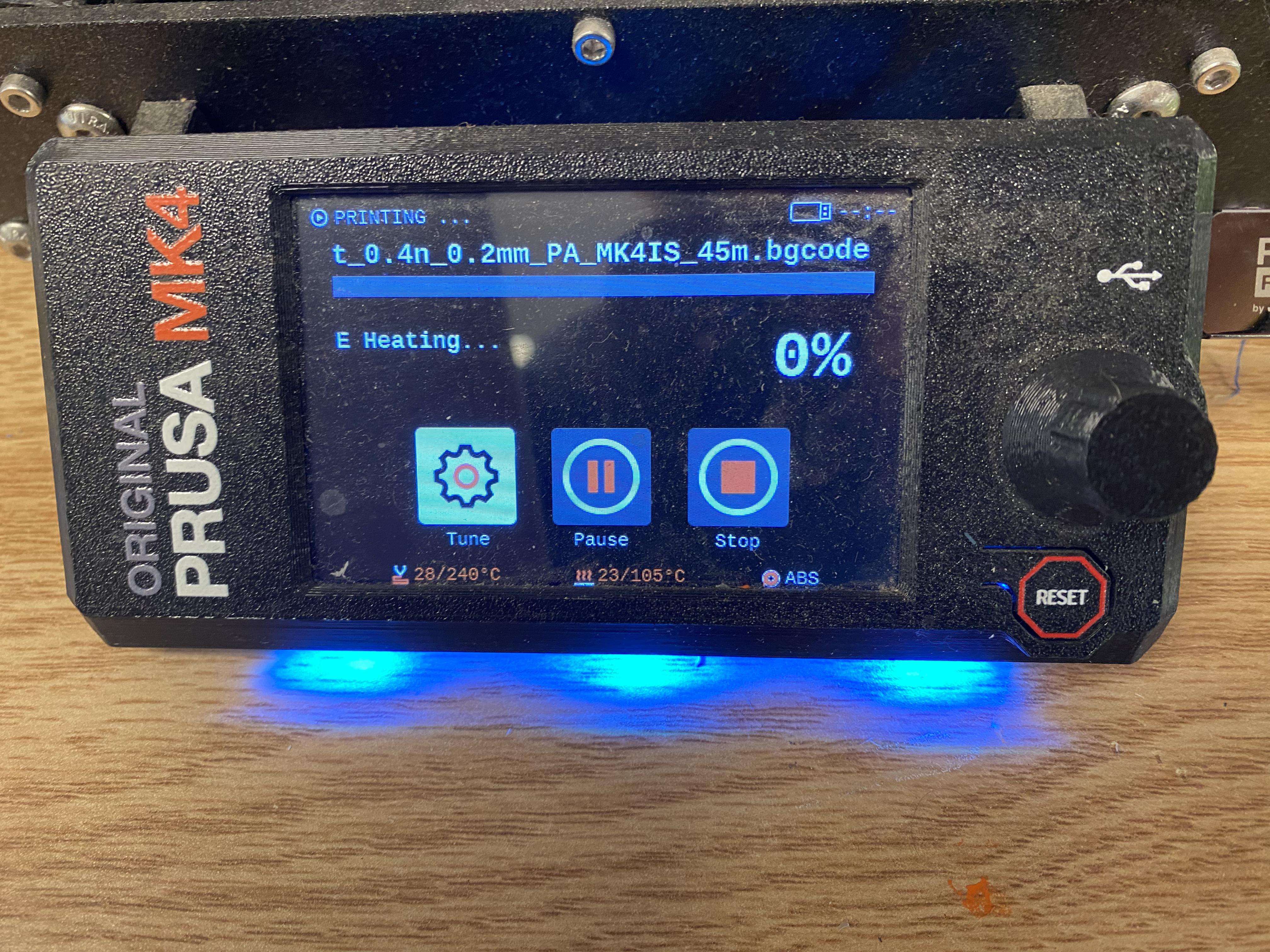
If this is the file you wish to print, simply click the knob and it will begin printing.
If the file doesn’t appear or the file that appears isn’t the file you wish to print, navigate to the home menu.
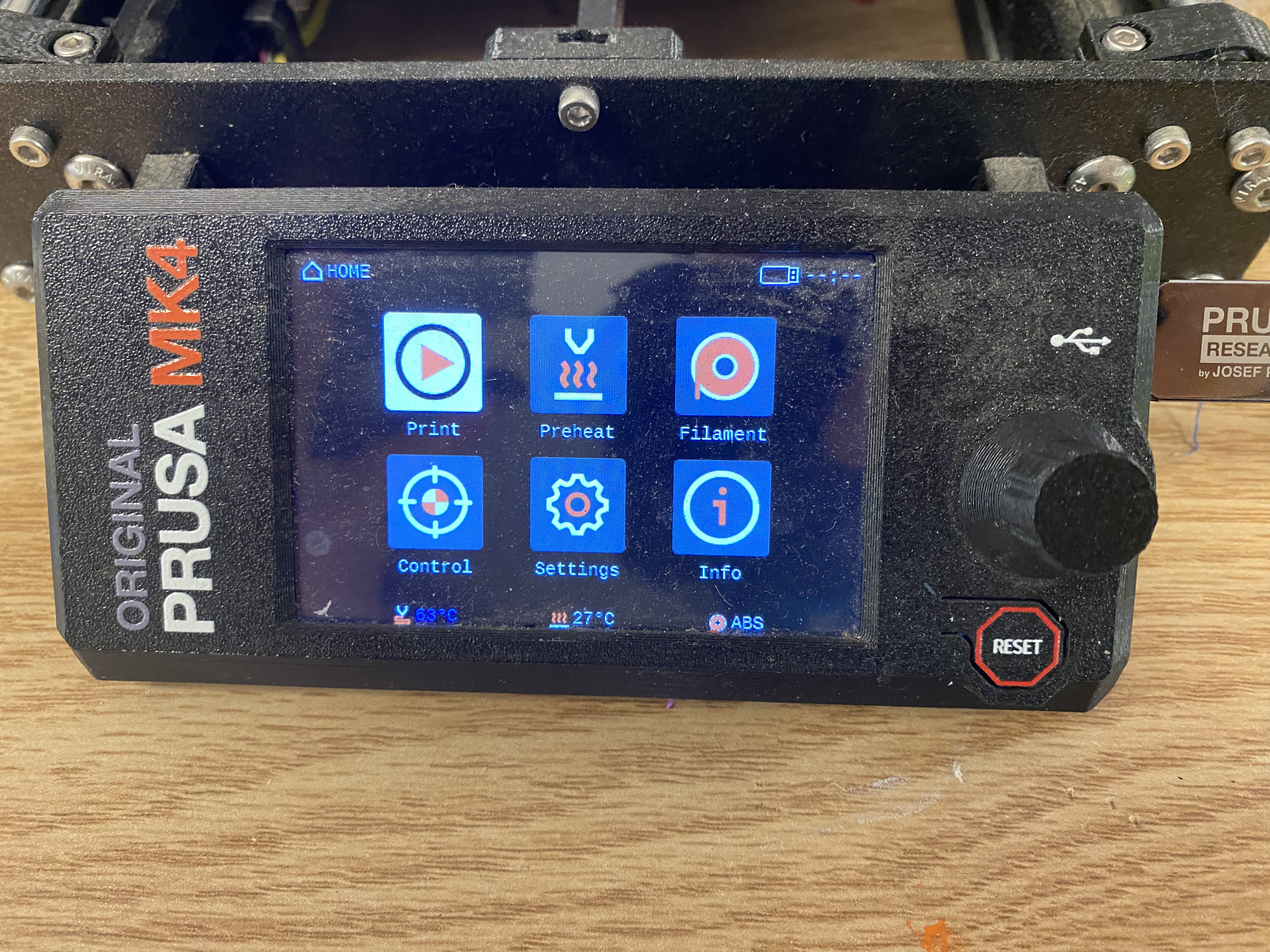
Select Print.
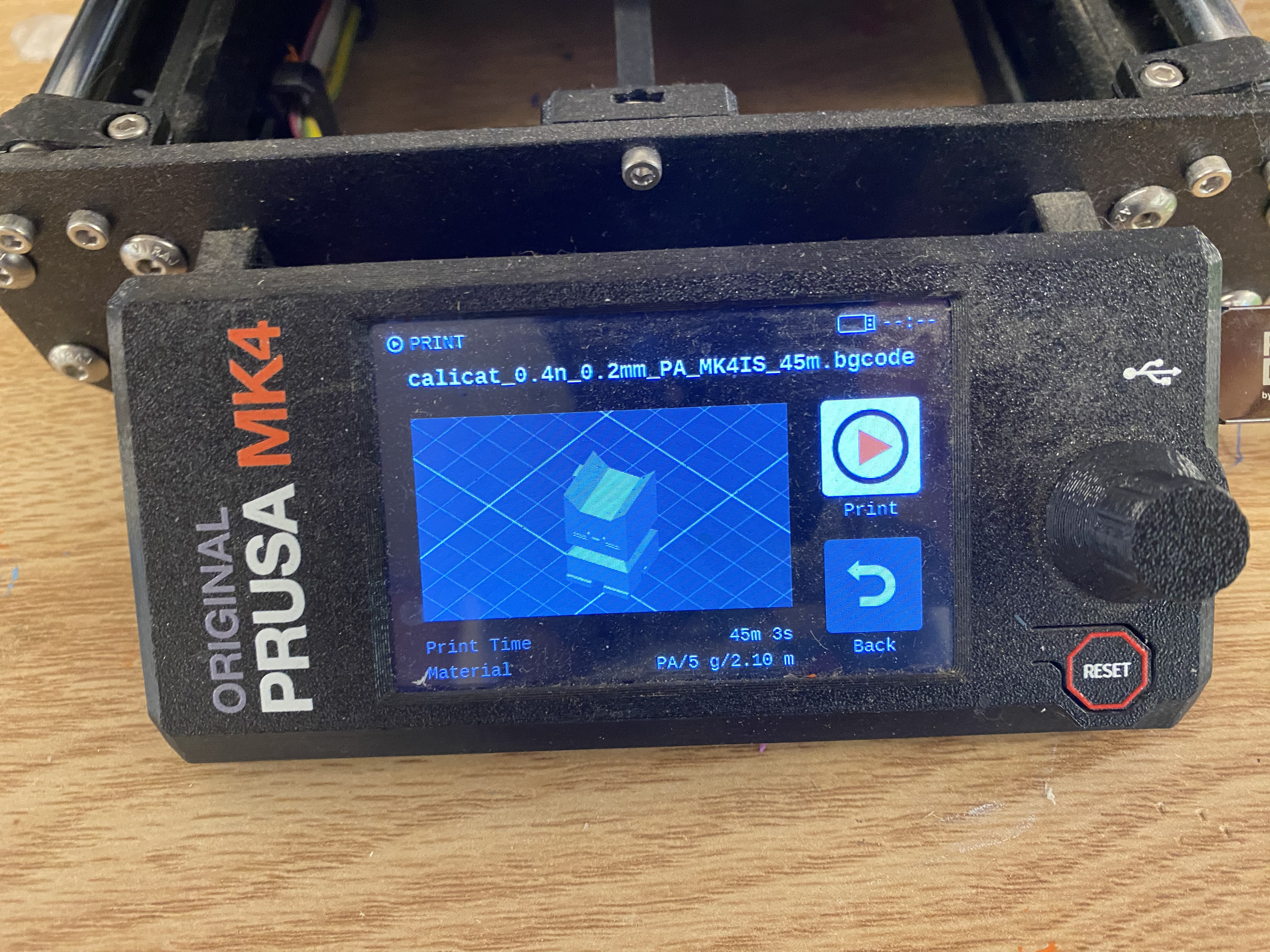
then select the name of your file you wish to print. A menu will appear allowing you to confirm your selection.
Hit print once you confirm it is the right file.
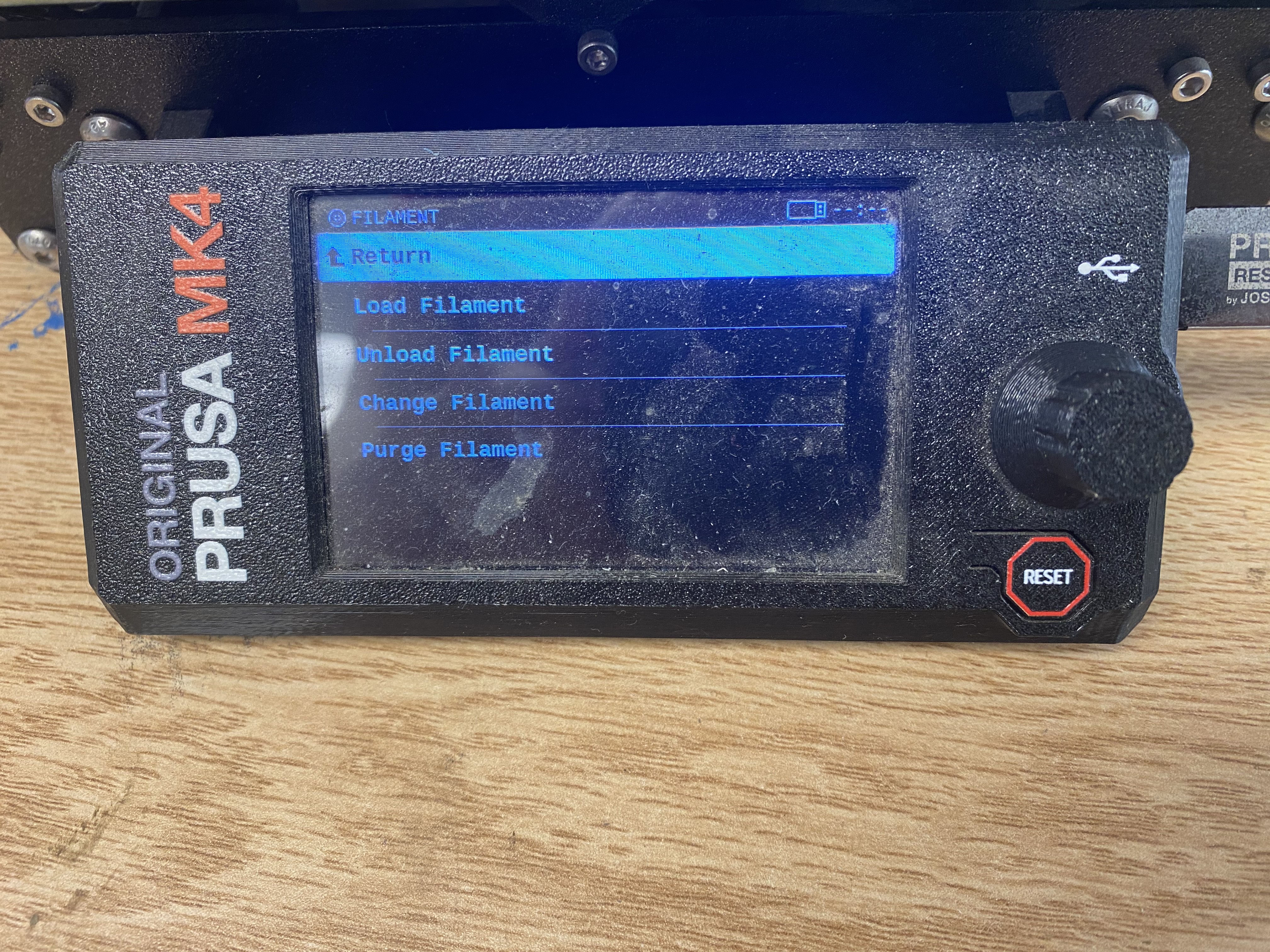
To change filament, navigate to the Filament button on the home screen by rotating the dial, and pressing the dial to select. There you will be presented with 4 options, Load, Unload, Change, and Purge.
Load will let you load a filament into the printer. Follow the instructions on the screen.
Unload will let you unload the currently stored filament. Follow the instructions on the screen.
Change will first unload and then load filament. Follow the instructions on the screen.
Purge will eject a small amount of the loaded filament. Follow the instructions on the screen.
The Prusa Mark 4s are arguably the best printers we have, with a great mix of speed and accuracy, and they can be run at up to 500% speed with a good level of accuracy. The guides to print with these are below:
To upload files to the Prusa Printers first get the stl, obj, or other 3D file type and open it with PrusaSlicer either through opening through File Explorer or dragging the file into the PrusaSlicer application, or clicking the (
) icon and selecting the file.
Once the file loads in, you can move it around the buildplate and change it to your likings, or upload more files by dragging them into the application window.
In the top menu you will see a list of options.
(
) will allow you to add a file from file explorer
(
) will delete the current selected object
(
) will clear the buildplate of all objects
(
) will arrange the models on the buildplate
(
) will copy the selected object
(
) will paste from the clipboard
(
) will add a copy of that object
(
) will remove a copy of that object
(
) will split a separated object into multiple objects
(
) will split a separated object into multiple parts
(
) will let you search features
(
) will bring up the variable layer height menu which is beyond the scope of this guide and should not be used without a more comprehensive understanding of the printers.
(
) undoes the last action
(
) redoes the last undo
To move the print around the print bed, first click the item you wish to move, then either drag your shape to its intended position, or click the (
) icon and you will see three arrows pop up around your shape.
Once that happens you can either move it on the main axis by dragging those arrows, or just grab and drag the object to wherever you want it.
You can also set its exact position with the menu on the bottom right of the screen.
There you will also see a menu with two options World Coordinates and Object Coordinates.
World Coordinates lets you set position relative to the bed, with 0,0 being at the bottom left corner.
Object Coordinates lets you shift the object from its current position and will move it as far as you put in. You can also switch to measuring in inches by checking the inches box.
To scale your object, select the object, then select the (
) icon, and three lines with boxes will appear, as well as a few orange boxes in a square around it.
You can grab any of the three to stretch the object in the direction of that line, or instead grab one of the orange boxes to stretch in all directions equally.
You can also set its exact scale with the menu on the bottom right of the screen.
Scale Factors allows you to set the scale relative to the original object.
Size \[World\] allows you to set the numeric size along all three axis. You can also switch to measuring in inches by checking the inches box.
If the lock icon is closed, the object will retain it’s original proportions and scale axis equally. If it is open you can manipulate the three separately.
The rewind icon will set the object to it’s original dimensions.
To rotate your object, select the object, then select the (
) icon, and three rings will appear.
You can grab these rings and rotate them to rotate the object how you would like it to print. Keep in mind where the front of the bed is, signified by where it is written Prusa MK4.
It is recommended to rotate the object so that the least amount of overhang is achieved:
And the maximum amount of the print is touching the build plate:
You can also set its exact rotation with the menu on the bottom right of the screen.
Putting numbers in the text boxes will rotate the object in the direction of the arrows that appear as many degrees as you insert in the box.
You can also click the (
) icon and your object will show white planes. Clicking one of these will orient the object so that the selected plane is touching the buildplate.
To cut your object in 2 pieces, hit the (
) icon, and a menu will appear, as well as the cutting plane.
In the menu you will see a selection box labeled Mode. Inside there are two options, Planar and Dovetail.
When you select planar, you should first select where you would like to cut the file. The plane will automatically appear and shade the two halves of the object different colors. To adjust this cut, you can either drag the red and green arrows to tilt the plane, or grab and drag the grey ball to move the plane.
You can also set the height of the cut off of the buildplate automatically in the menu.
This will create a smooth cut into two pieces.
If you want to instead have a more secure way of joining these pieces after you cut, press the Add Connectors button.
From there it will hide one of the two halves, and allow you to place connectors. You will see 3 options for the type of connector, Plug, Dowel, and Snap.
Plug creates a small protrusion from one side, and a matching hole in the other. You can select whether you would like a prism or frustum shape:
As well as what shape you would like it to be, triangle, square, hexagon, or circle:
Dowel creates holes in both halves of the print as well as a small dowel to join the two.
Again you can choose the shape of the dowel, triangle, square, hexagon, or circle:
Snap creates a small mechanism which will snap into a hole in the other piece.
For all of these options, you can change the depth out of or into the piece, the horizontal size of the peg, and the rotation around its center.
For the snap you can alter the bulge of the top section and space between connectors. Hitting the rewind icon will pu tit back to default settings.
Once you are happy with the settings, you can click anywhere on the orange surface to place the connector where you click.
Hit confirm connectors once you are happy with the connector position and settings or cancel to return to the cut menu.
Dovetail will create a unique joint between the two pieces, where one will be able to slide into the other.
The plane will automatically appear and shade the two halves of the object different colors. To adjust this cut, you can either drag the red and green arrows to tilt the plane, grab and drag the white ball to rotate the groove, or grab and drag the grey ball or cube to move the plane.
You can also set the height of the cut off of the buildplate automatically in the menu.
From there you can adjust the settings of the dovetail joint, with the sliders provided. Hitting the rewind icon on any slider will set that slider back to it’s default position.
Below the other settings, you will see a section named Cut Result. There you will see a column for each half of the cut. If the check box is selected the cut will generate that pice and not discard it.
You can then select how to place the object once it cuts. Keep Orientation will keep the object as it is before that cut. Place On Cut will lay the object along the plane of the cut. Flip Upside Down will invert the object.
If you have selected planar and not added connectors, you can at the bottom select to cut into parts instead of objects, which will leave the two sides connected but allow them to have their settings edited separately with the left parts menu.
If you press the (
) icon you can add supports in specific spots by “painting” with your mouse. Click and drag to add supports where you drag, and right click and drag to block supports in the certain spots you “paint”.
You can also automatically paint areas, edit where can be painted, and edit your “brush” shape in the menu below.
If you press the (
) icon you can control where each layer of the print starts and ends, creating a small slightly visible seam.
Clicking and dragging will force the printer to place a seam there, and right clicking and dragging will stop seams in that area.
You can also change the shape of your brush and view options in the menu that appears.
To measure your object, select the object, then select the (
) icon. You can then click individual faces, edges, and points to measure the distance, angle, and areas of the parts selected.
When you measure a length, a (
) icon will appear, and allow you to change the length highlighted and scale the rest of the model to enforce that length.
In the menu you can either hit the Restart Selection button to clear your selection, or click the (
) icon next to the measures to copy the numbers there.
Once you are happy with the object’s placement, move to the Printer Settings section.
Once you are satified with the object placement, move to the right menu.
Here you will see a list of settings for layer heights:
0.1 mm will be the most precise setting, good for visual detail or mechanical functionality.
0.15 mm has both SPEED and STRUCTURAL options, choose SPEED for a faster print, or STRUCTURAL for a sturdier print.
0.2 mm has the same options, but both will be faster but lower quality than their 0.15 mm counterparts.
Here you can select the type of filament to be printed. Make sure this matches what is loaded in the printer before printing.
Here you select which printer to use. Select Original Prusa MK4 Input Shaper 0.4 nozzle.
Supports are how the printer helps overhangs print, as the printer must always work from bottom to top and cannot print without a surface to print on. Support can be selected and deselected, but is recommended to use whenever there are overhangs or floating objects in your print.
The options in the dropdown designate where supports generate, and gives 4 options, None, Support on Buildplate Only, For Support Enforcers Only, and Everywhere.
None will not create any supports.
Support on Buildplate Only will only support overhangs over the buildplate, and overhangs that have other bits of object below will not generate support.
For Support Enforcers Only only puts supports in specified spots, either by you or the model itself.
Everywhere means any overhang will be supported, no matter where on the print it is.
It is recommended to use Everywhere when overhangs are present.
This will allow you to dictate how much of the interior of the print is filled in, with 0 meaning no fill, and 100 meaning completely full.
Anything down to 10% will be self supporting enough, although 20% is recommended for nearly every print. 70% is the absolute maximum you need to go for a high strength print, however this should only be used if extreme strength is needed.
The brim helps prints stick to the print bed and avoid shifting and warping off of the bed. It is recommended to keep this setting selected for any print.
In the part menu, you can select and change settings for specific parts by clicking the (
) icon.
The full scope of this will not be covered on this website.
In the top left you will see tabs wil more settings. These can affect more specific things about the print and printer but that is only recommended to use if you are more comfortable with the printer and how it works.
Once your settings are as desired, move to the Slicing Files section.
Once you have set up your print how you want it, press the Slice button in the bottom right.
insert
Once you do this, you will se a new tab appear, Preview. This allows you to look at the exact printing path of the printer.
insert
Here you can use the slider on the right to move up and down the layers, showing each layer path individually, and then use the bottom slider to watch the exact movement path for that layer.
You can add breaks, custom g-code, and filament swaps into your print from here, by sliding the slider on the right to where you want and either clicking the (
) icon to add a color swap, or right clicking to choose between pause, custom g-code, and color swaps.
Pauses will stop the print and let you either add parts into the print or check the print, and resume when you press a button on the printer. Add custom g-code will have the printer run a set custom g-code file. Color swap will do the same as regular clicking.
If you choose to do a filament swap, make sure you are using the same type of filament.
You can also see specific parts of the print broken down by type of print and shaded different colors, as well as a menu of options at the bottom. This lets you view more specific information about the print.
Once you have done this, move to the Transferring to Printer section.
Once you have your gcode file, take the USB drive out of the printer and plug it into the computer. You can ignore any windows that pop up after doing this. Navigate back to PrusaSlicer and look to the bottom right. Click the (
) icon and hit Save when the window appears.
Wait until the box at the bottom reads Exporting Finished then hit the eject icon. It is safe to remove the USB once the box reads Successfully Unmounted.
Finally plug the drive back into the printer. Once you have done this move to the Printing section.
Once you load the USB drive back into the printer, if the file you wish to print was recently uploaded to the USB it will appear automatically.
If this is the file you wish to print, simply click the knob and it will begin printing.
If the file doesn’t appear or the file that appears isn’t the file you wish to print, navigate to the home menu.
Select Print.
then select the name of your file you wish to print. A menu will appear allowing you to confirm your selection.
Hit print once you confirm it is the right file.
To change filament, navigate to the Filament button on the home screen by rotating the dial, and pressing the dial to select. There you will be presented with 4 options, Load, Unload, Change, and Purge.
Load will let you load a filament into the printer. Follow the instructions on the screen.
Unload will let you unload the currently stored filament. Follow the instructions on the screen.
Change will first unload and then load filament. Follow the instructions on the screen.
Purge will eject a small amount of the loaded filament. Follow the instructions on the screen.
The lulzbot is the simplest printer, although has some filament limitations. To use it use these guides:
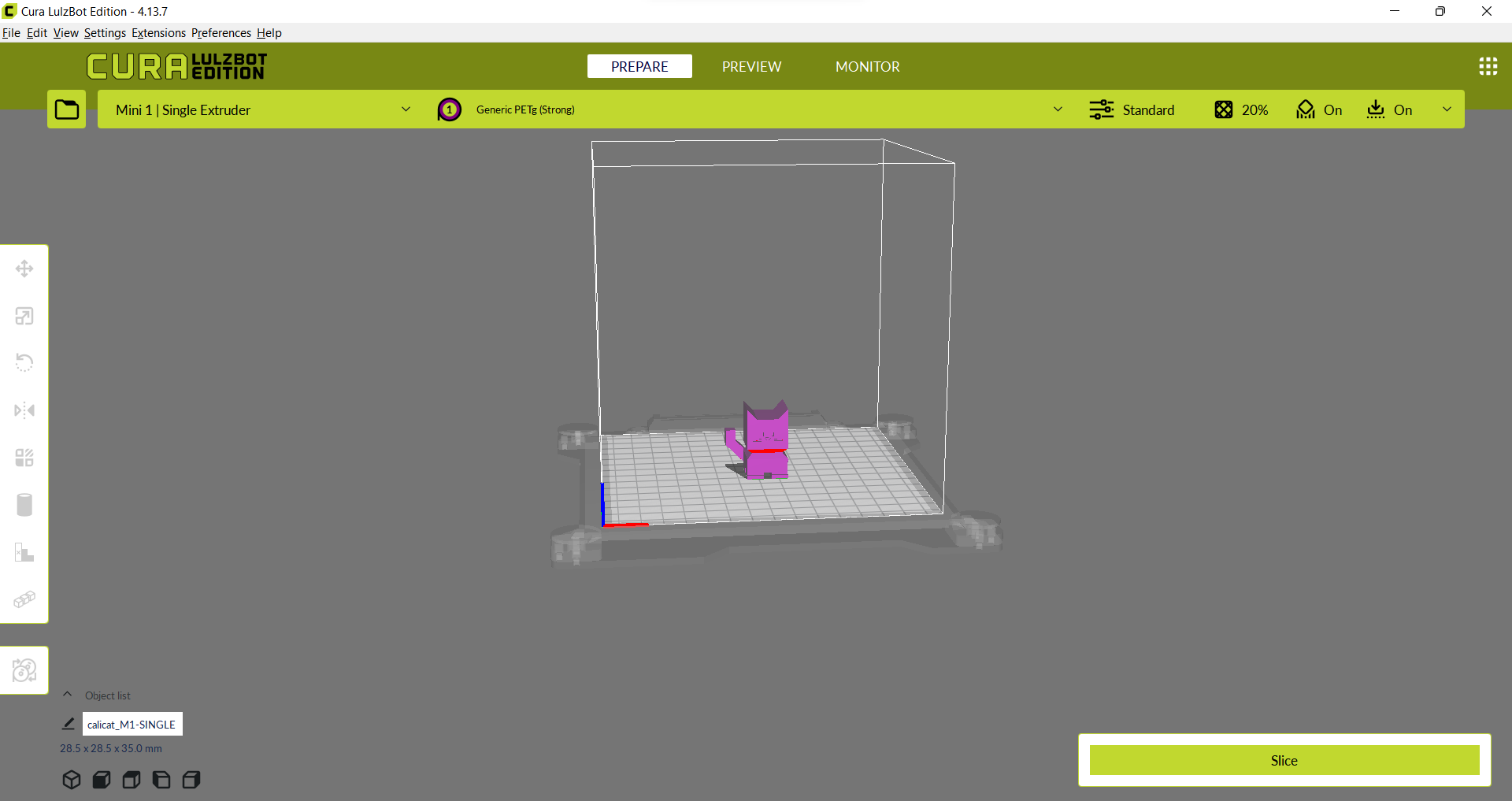
To upload files to the Ultimaker first get the stl, obj, or other 3D file type and open it with Cura LulzBot Edition either through opening through File Explorer or dragging the file into the Cura LulzBot Edition application.

Once the file loads in, you can move it around the buildplate and change it to your likings, or upload more files by dragging them into the application window.
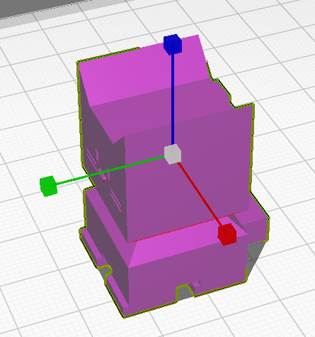
To move the print around the print bed, first click the item you wish to move, then click the (
) icon and you will see three arrows pop up around your shape.
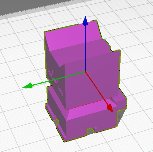
Once that happens you can either move it on the main axis by dragging those arrows, or just grab and drag the object to wherever you want it.
You can also set it’s exact position with the menu that appears next to the (
) icon.
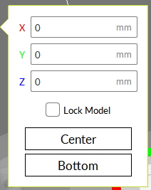
there you will also see two checkboxes, Lock Model and two buttons Center and Bottom.
Lock Model makes it so the model cannot move other than by changing the numbers in the menu, dragging the model or arrows will no longer move it.
Center will move the object to the center of the buildplate.
Bottom moves it’s lowest point to be touching the print bed.
It is recommended to keep the Lock Model unselected and hit Bottom before slicing.
To scale your object, select the object, then select the (
) icon, and three lines with boxes will appear.
You can grab any of the three to stretch the object in the direction of that line, or instead grab the central box to stretch in all directions equally.
Again a menu will pop up with certain options. The text boxes allow you to set the length, width, or height of the object by measured size or percentage of the original model.
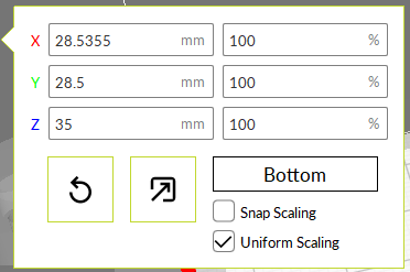
there you will also see two checkboxes, Snap Scaling and Uniform Scaling as well as a rewind icon, a ( ) icon, and a button that says Bottom.
Snap Scaling makes it so the object will snap between set sizes.
Uniform Scaling makes it so all the axis will scale uniformly, meaning any change to one axis will be matched in the other two to keep the proportions of the object the same.
The rewind icon will set the object to it’s original dimensions, and the (
) icon will set it to the max size the printer can print.
Bottom moves it’s lowest point to be touching the print bed.
It is recommended to keep the Snap Scaling unselected and Uniform Scaling selected unless you intentionally want a off proportion model.
To rotate your object, select the object, then select the (
) icon, and three rings will appear.
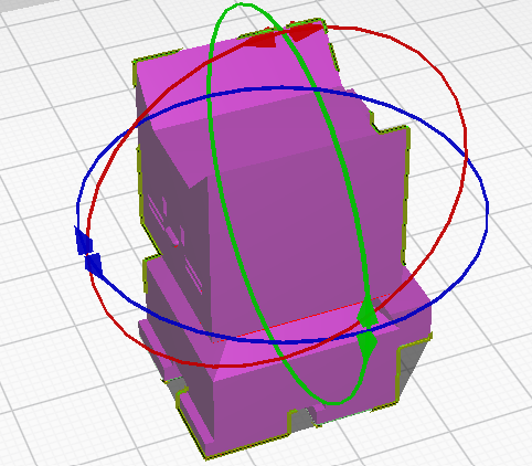
You can grab these rings and rotate them to rotate the object how you would like it to print. Keep in mind where the back of the bed is, signified by the lip where it is written Ultimaker S5.
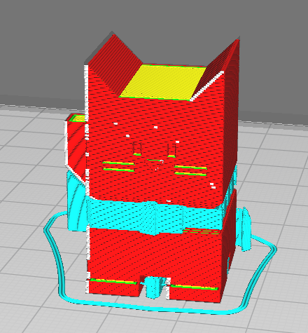
It is recommended to rotate the object so that the least amount of overhang is achieved:
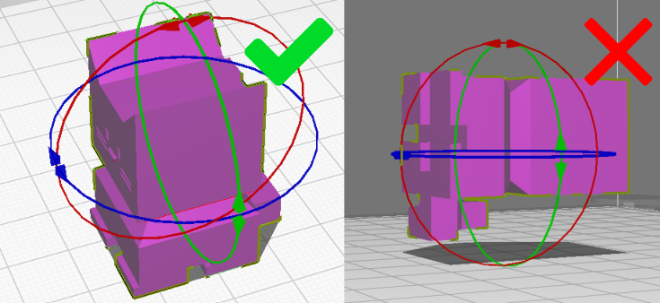
And the maximum amount of the print is touching the build plate, shown by the light blue highlight:
Again a menu with certain options will also appear next to the (
) icon.
The rewind icon will return the object to it’s original orientation.
the (
) icon will rotate the model as little as possible to ensure a flat surface is laying against the print bed.
the (
) icon will allow you to click on a face of the print and the program will lay it flat against the print bed. This feature is somewhat inconsistent so it may take a few tries to correctly align it.
Snap Rotation makes it so the print will only rotate in multiples of 15 degrees.
It is recommended to keep Snap Rotation selected unless a particular angle is needed.
When you select the (
) icon, 6 arrows will appear.
Clicking any of these arrows will mirror the object as if there was a mirror that the arrow was pointed directly into.
Clicking the (
) icon will allow you to change how the object prints.
The first icon is the default, and will follow the print settings that you set.
The second prints as if is is support for a different model, which will follow the support settings that you set.
The third will deal with overlapping objects, which is much more complicated, and a full description of the options can be found here: https://support.makerbot.com/s/article/1667417981430.
The last will remove all supports in the volume of the object, but will not print the object itself.
To create custom supports, select your object then hit the ( ) icon.
There you will see some options for how you want the support to generate.
Once you have set your desired shape, click where on the object you want to support and it will automatically support that spot.
The ( ) icon will block support in a cubic area, similar to the last option of the last tool.
To use this, click the model you want to remove supports from, click the (
) icon, and then click where you want the blocker. You can then edit the blocker as if it was any other object, using the tools above. The print will not generate any supports in the area of this block.
To duplicate your object, select the object and then hit the ( ) icon.
A menu will appear and allow you to set how many copies you want. Hit the Multiply button once you have set the desired number.
To add a pause or filament change to your print, select the object and hit the ( ) icon.
There a menu will pop up, with a box to specify what layer you want the filament change at. If instead you just want to pause the print, select the Pause Only box.
Once you are happy with the object’s placement, move to the Print Settings section.
Once you have your object oriented as desired, select your material.
At the top of the display there will be a dropdown menu to select material type.
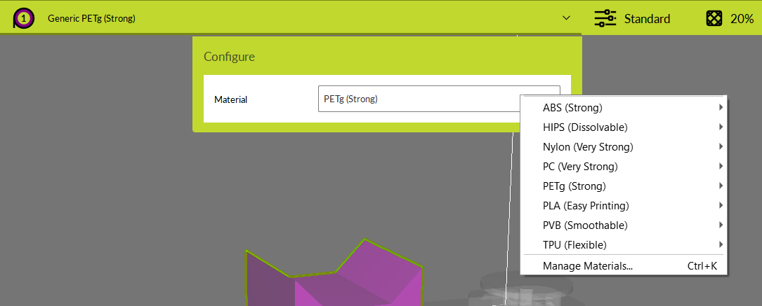
Click to show the options for material selection and select the one currently loaded in the printer.
Now move to the print settings menu. There you will see lots of options, which I will briefly review here.
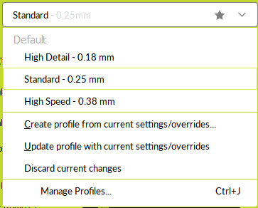
Firstly you will see a list of Profiles. These are the easiest way to select your settings.
High Detail prioritizes details and functionality. Use this for projects that need to look good or mechanically function.
Standard Is a mix of detail and speed. Use this for general printing.
High Speed is for quickly printing models that are prototypes or not particularly valuable. Use this for testing and quick prints.
There are lots of other settings that can be adapted, we will briefly review the most important.
Int the infill section, the Infill Density dropdown will allow you to dictate how much of the interior of the print is filled in, with 0 meaning no fill, and 100 meaning completely full.
anything down to 10% will be self supporting enough, although 20% is recommended for nearly every print. 70% is the absolute maximum you need to go for a high strength print, however this should only be used if extreme strength is needed.
This allows for a selection of how the infill will be created, and the options are shown below:
Grid
Lines
Triangles
Trihexagon
Cubic
Cubic Subdivision
Octet
Quarter Cubic
Concentric
Zig Zag
Cross
Cross 3d
Gyroid
Lightning
Triangle is the recommended setting but this choice has little effect on the overall print.
Supports are how the printer helps overhangs print, as the printer must always work from bottom to top and cannot print without a surface to print on. Support can be selected and deselected, but is recommended to use whenever there are overhangs or floating objects in your print.
Adhesion provides a way for you to help the print stick to the print bed better. There are a few options for this.
Skirt Simply outlines the shape before printing it, this does not help much with adhesion though.
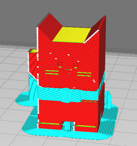
Brim creates a brim of filament around the bottom layer of your print.
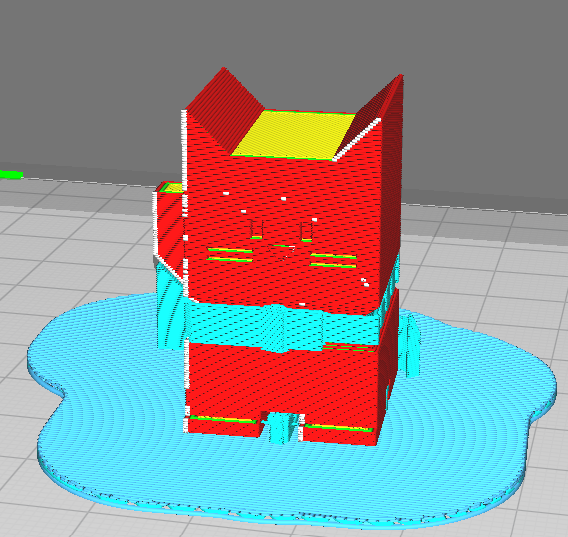
Raft creates a small 3d bubble below your print that is very large.
None generates no adhesion support
It is recommended to select Brim for any print with only a small area touching the bed.
Vase mode ignores all other settings and prints only the outer wall of your print in a spiral pattern.
Many other specific settings can be tuned however there are far too many to cover in this guide, so look to a more specific guide on the Cura LulzBot Edition Slicer for information on that.
Once you have your preferred settings set, move to the Slicing Files section.
Once you have set up your print how you want it, press the slice button in the bottom right.

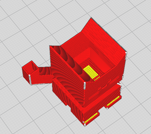
Once you do this, you will see a new tab appear, Preview. This allows you to look at the exact printing path of the printer.
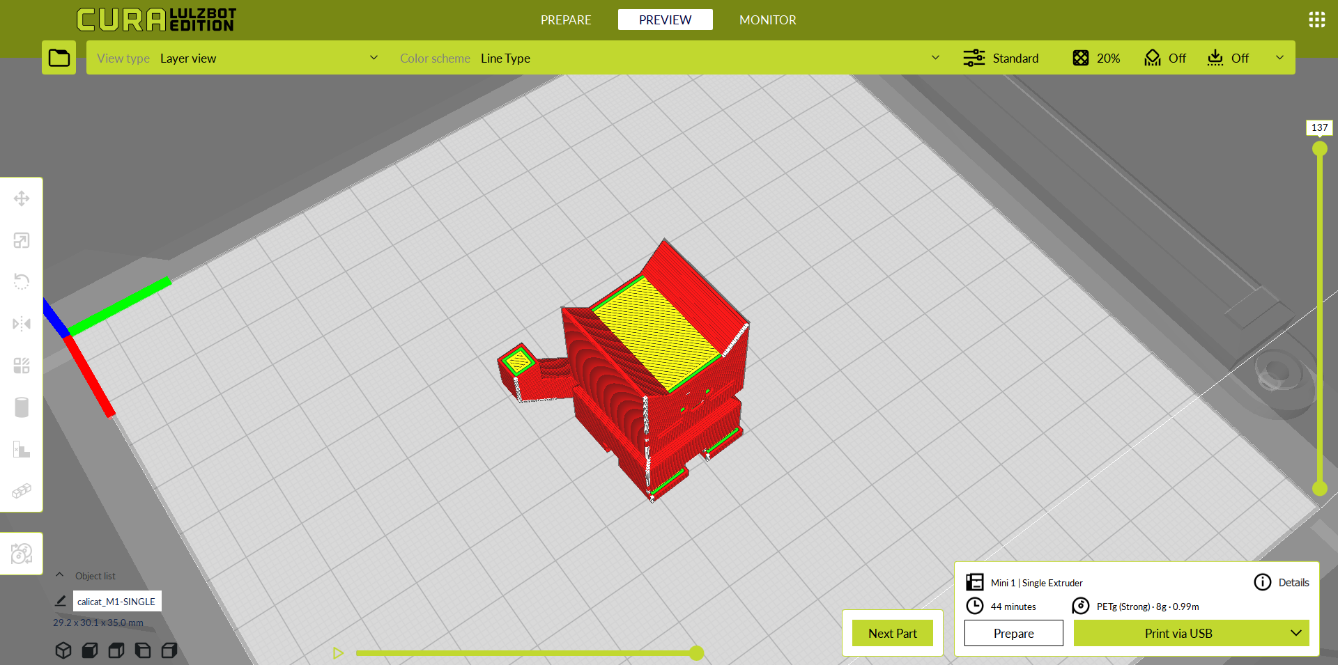
Here you can use the slider on the right to move up and down the layers, showing each layer path individually, and then use the bottom slider to watch the exact movement path for that layer.
Once you have done this, move to the Transferring and Printing section.
To transfer your print to the printer, first make sure the computer is connected to the printer by USB cable, and the printer is on. Then press Print via USB in the box in the bottom right and a new menu will appear with the print settings.
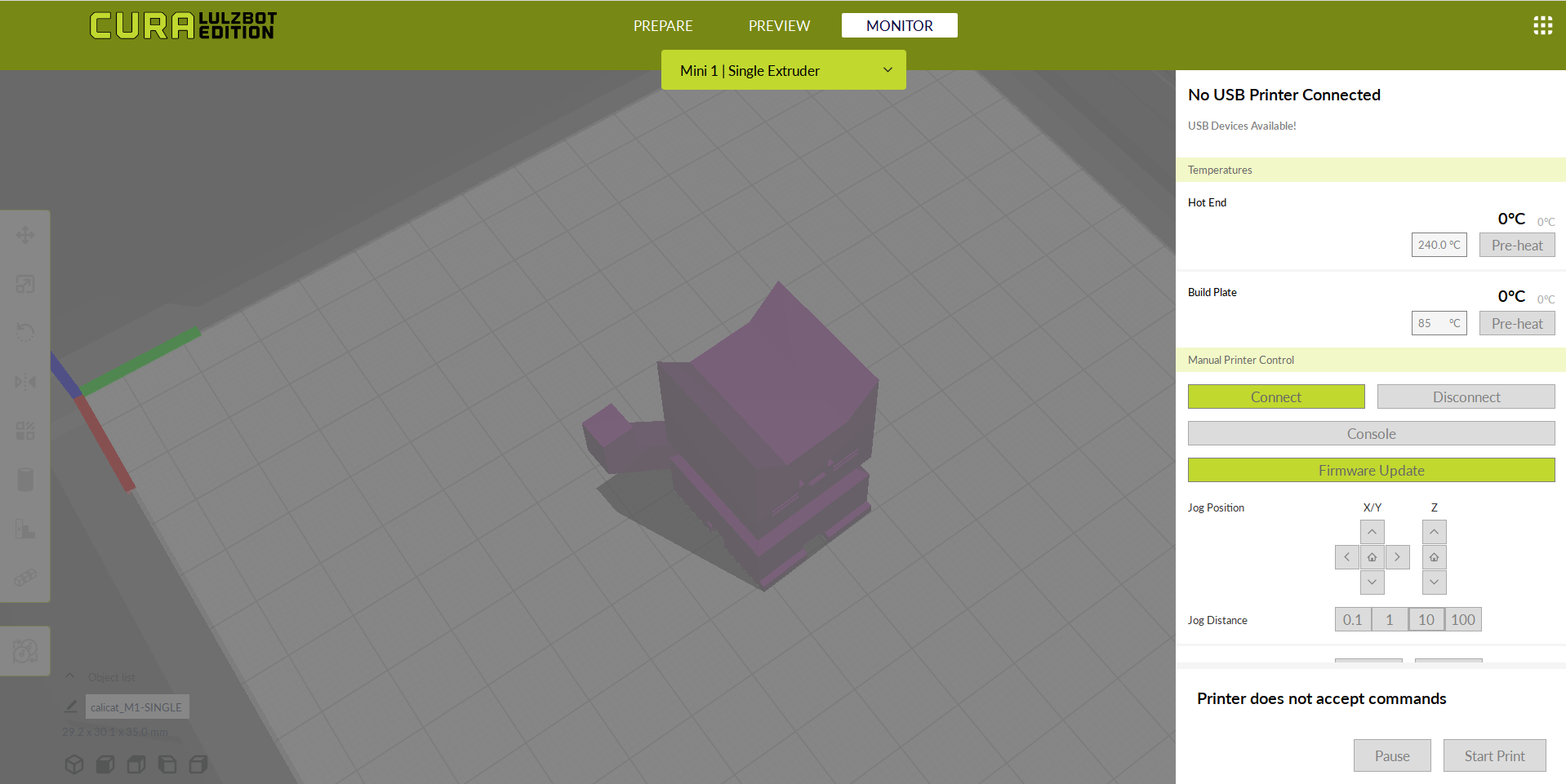
Click the Connect button and wait a few seconds. Eventually the box at the top will read Connected to Printer.
Once that happens move back to the right menu. Click the Pre-Heat buttons in the Hot End and Build Plate Sections.
Once the printer is heated, hit the Start Print button to begin the print.
To change filament on the LulzBot, first open the Cura LulzBot application, and navigate to the monitor tab.
Click the Connect button and wait a few seconds. Eventually the box at the top will read Connected to Printer.
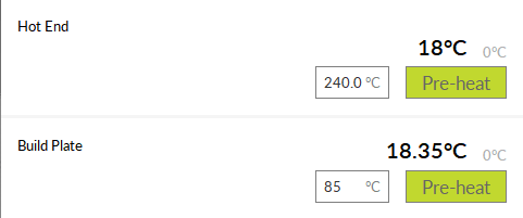
Once that happens move back to the right menu. Click the Pre-Heat buttons on the Hot End section only.
Then wait until the larger black number changes to match the smaller grey number.
Now scroll down to the Manual Printer Control section.
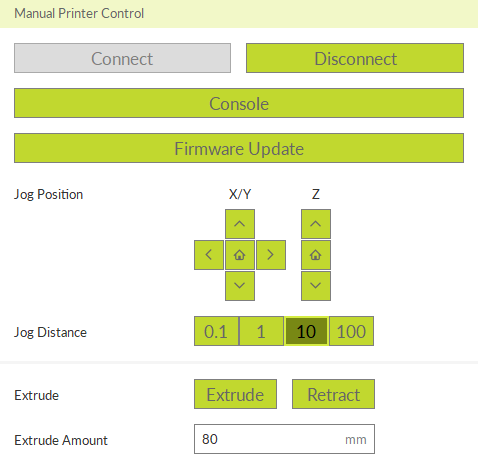
Change the number in Extrude Amount to 100, then hit the Retract button. Then gently pull upwards on the filament.
To load filament, use the same process as above, but set the number to 80 instead of 100 and hit the Extrude button while gently pushing the filament in.